What this code means
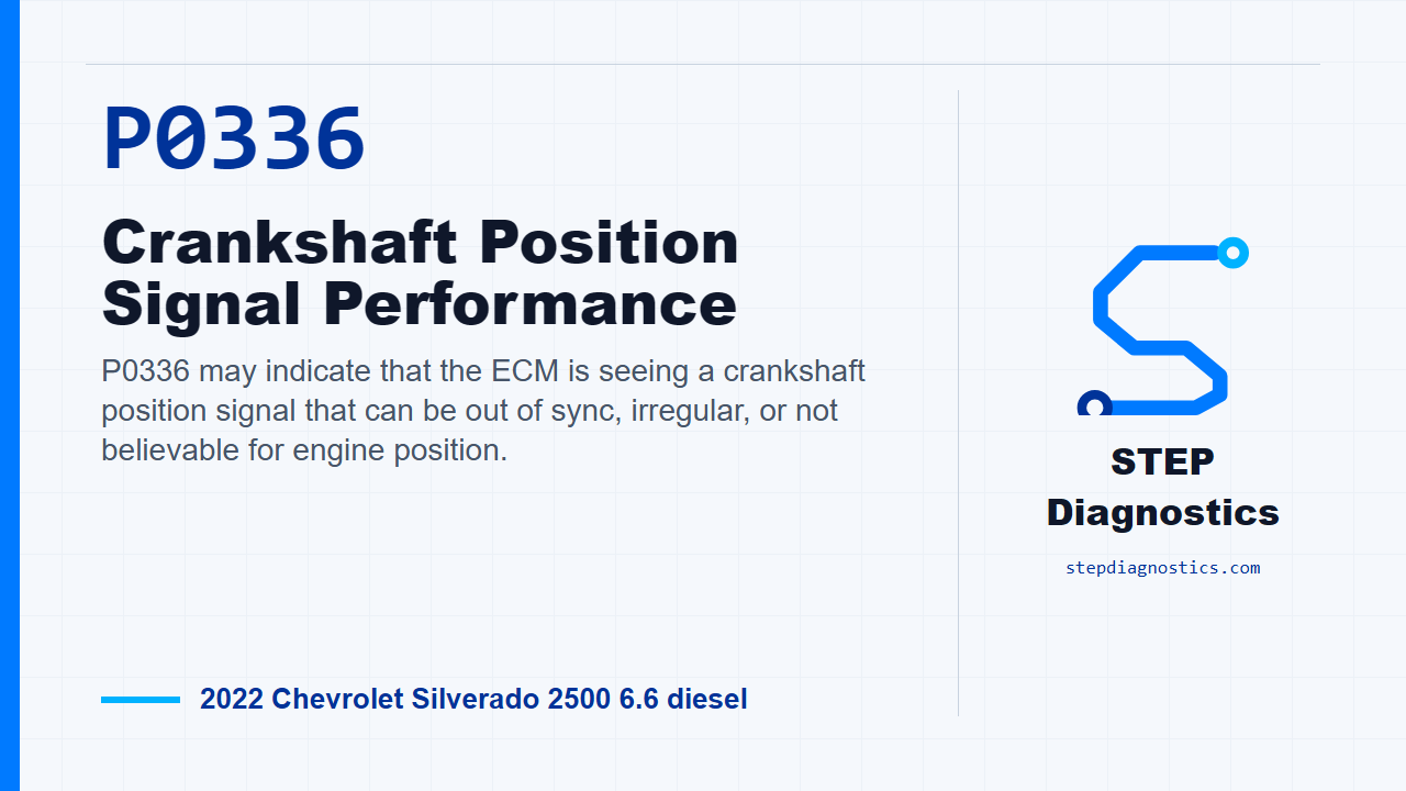
P0336 may indicate that the ECM is seeing a crankshaft position signal that can be out of sync, irregular, or not believable for engine position.
What the vehicle may do
- The vehicle may crank longer than normal.
- The engine may run rough, stumble, or stall.
- The concern can be intermittent and may appear only under certain operating conditions.
- A no-start or hard-start condition may be possible.
Possible fault areas
- A possible crankshaft position sensor circuit issue.
- A possible sensor connector, terminal, or harness issue.
- A possible ECM-side circuit issue.
- A possible mechanical signal source or timing-related issue.
Diagnostic path
Set the direction first
On this 2022 Chevrolet Silverado 2500 with the 6.6 diesel, P0336 means the ECM may be seeing a crankshaft position signal that is out of sync, irregular, or not believable for engine position. The truck may crank longer than normal, run rough, stumble, stall, or show up as an intermittent concern. Keep the possible fault areas broad at first: the crank sensor circuit, the sensor and connector, the ECM side of the circuit, and possible mechanical signal source or timing-related issues. Start with the basic system checks, then follow a structured diagnostic approach. If other codes are present, especially reference-voltage or cam and crank signal concerns, understand those first so you do not chase the wrong symptom.
Know the monitor gates and crank signal logic
Before testing, keep the monitor logic in mind. The enable gates include MAF Sensor = Greater than 2.0 g/s and Engine Speed = Greater than 450 RPM, and the MAF gate appears again in the shared crank diagnostic path as MAF Sensor = Greater than 2.0 g/s. For the crank signal, the ECM can flag a no-signal or sync problem when the crankshaft position sensor shows No Signal — For greater than 4 s, No Signal — For greater than 0.3 s, or No Signal — During 2 engine revolution(s). For P0336-type sync concerns, the important logic includes Signal synchronization lost 10 times within 10 s., Sync gap not detected — For greater than 0.4 s, Sync gap not detected — Since last starter engagement — For greater than 1.5 s, and Not between 51 and 65 pulses — During 1 engine revolution(s) — For 8 out of 10 engine revolutions. The circuit also uses a 5 V Reference, and the crank signal source is based around 58 teeth or invisible magnetic segments, 60 segment spacing, and 2 missing segments. Treat those as monitor and signal-structure details, not as parts to replace by themselves.
Initial checks before circuit testing
With the ignition on and the vehicle in service mode, make sure the shared reference-voltage fault is not set. If it is set, handle that reference circuit problem before continuing with P0336. If that check passes, run the engine and see if P0336 sets. If it sets while the engine is running, go straight into circuit testing. If it does not set, watch the crankshaft position active counter on the scan tool. That counter should increment. If it does not increment, move into circuit testing. If it does increment, watch the crankshaft position resync counter. It should stay at 0 Counts, and the engine should not stumble/stall.
Check for an intermittent before tearing in
While monitoring that resync counter, wiggle the harness and connectors at the B26 crankshaft position sensor and at the K20 ECM. If the counter goes greater than 0 counts, repair the wiring, terminals, or electrical connectors as necessary. If it stays at 0 counts, reproduce the operating conditions for the monitor, or reproduce the captured conditions from the vehicle data. Then verify the DTC does not set. If it sets during that drive or run check, continue into the circuit tests.
Low reference and 5 V reference checks
Power the vehicle and all systems off, allow the power-down time up to 2 min, then disconnect the B26 crankshaft position sensor. First, check the low reference circuit at terminal 2 to ground. You want less than 10 Ω. If it is 10 Ω or greater, disconnect the K20 ECM and check that low reference circuit end to end from the component harness to the control module harness. You want less than 2 Ω. If it is 2 Ω or greater, repair the open or high resistance in the circuit. If it is less than 2 Ω, that points to replacing the K20 ECM. If the original low reference check was less than 10 Ω, continue to the 5 V reference. Turn the ignition on with the vehicle in service mode and test terminal 1 to ground. The expected range is 4.8 to 5.2 V. If it is less than 4.8 V, turn the vehicle off, disconnect the K20 ECM, and test terminal 1 to ground for infinite resistance. Anything less than infinite resistance means repair the short to ground. If it is infinite resistance, check the 5 V reference circuit end to end for less than 2 Ω. If it is 2 Ω or greater, repair the open or high resistance. If it is less than 2 Ω, that points to replacing the K20 ECM. If the 5 V reference is greater than 5.2 V, turn the vehicle off, disconnect the K20 ECM, turn the ignition back on in service mode, and check terminal 1 to ground for less than 1 V. If it is 1 V or greater, repair the short to voltage. If it is less than 1 V, that points to replacing the K20 ECM. If the 5 V reference is between 4.8 and 5.2 V, move on to the signal circuit.
Signal circuit and component decision
For the signal circuit, rapidly tap a 3 A fused jumper wire between signal circuit terminal 3 and ground. The crankshaft position active counter should increment. If it does not increment, turn the vehicle off, disconnect the K20 ECM, turn the ignition on in service mode, and test signal terminal 3 at the component harness to ground for less than 1 V. If it is 1 V or greater, repair the short to voltage. If it is less than 1 V, turn the vehicle off and test that same signal circuit to ground for infinite resistance. Anything less than infinite resistance means repair the short to ground. If it is infinite resistance, test the signal circuit end to end for less than 2 Ω. If it is 2 Ω or greater, repair the open or high resistance. If it is less than 2 Ω, that points to replacing the K20 ECM. If the active counter does increment during the fused-jumper test, verify P0336 is not set. If it is still set, check the physical and mechanical conditions around the crankshaft position sensor and signal source, including sensor installation, connector condition, reluctor alignment, and timing-drive play. If a condition exists, repair or replace as necessary. If those checks are normal, test or replace the B26 crankshaft position sensor.
Verify the repair
Keep verification separate from the fault isolation. After the repair is completed, verify the repair and confirm the code stays gone. If a Service Emission System or Service Exhaust Fluid System message is displayed, run the Reductant System Tamper Warning Service Bay Test. The takeaway is simple: prove the reference, ground, and signal circuits first, watch the crank counters under movement and operating conditions, and only then make the component call. For more diagnostic training, visit stepdiagnostics.com.
Final check
P0336 is often best handled by proving the power, ground, signal, and synchronization behavior before making a component decision.
For more guided automotive diagnostics, visit STEP Diagnostics.