What this code means
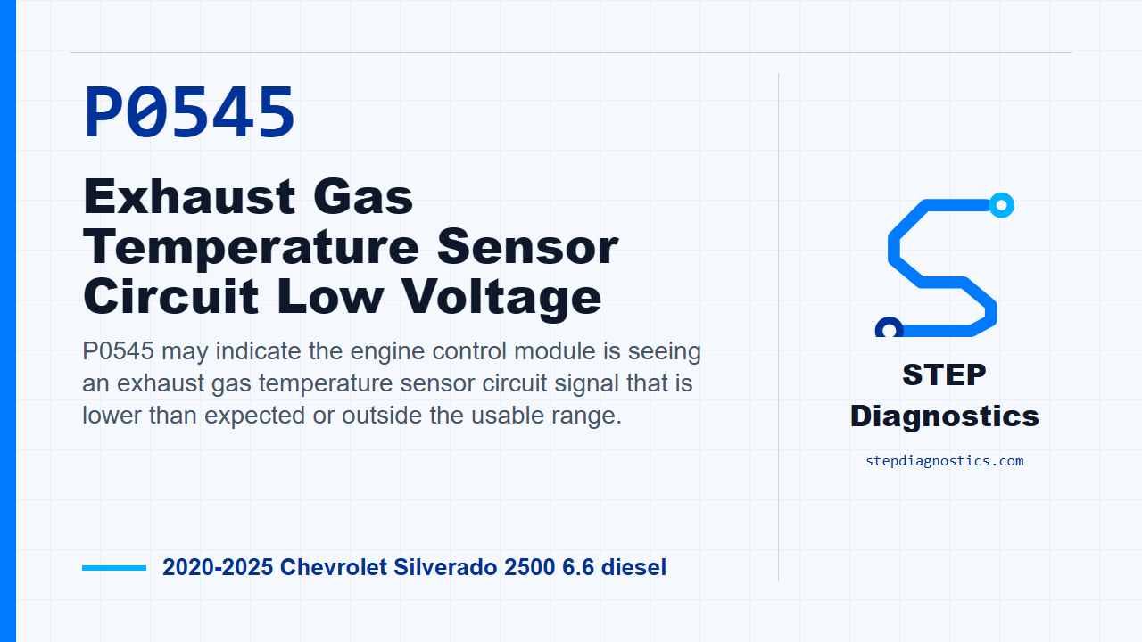
P0545 may indicate the engine control module is seeing an exhaust gas temperature sensor circuit signal that is lower than expected or outside the usable range.
What the vehicle may do
- The vehicle may display an emissions-related warning message.
- The code may set with little or no noticeable driveability symptom.
- The exhaust temperature reading on a scan tool may be implausible, unstable, or out of range.
Possible fault areas
- Possible sensor fault.
- Possible signal circuit fault.
- Possible low reference circuit fault.
- Possible connector, terminal, or harness contact issue.
- Possible control module involvement after circuit checks are proven.
Diagnostic path
Opening context
On this Silverado diesel, P0545 is an exhaust gas temperature sensor circuit fault. In plain terms, the control module may be seeing an exhaust temperature signal that is lower than expected or outside the usable range, and the truck may turn on an emissions warning or store the code without an obvious driveability complaint. The fault area can be the sensor, the signal circuit, the low reference circuit, connector or terminal contact, or in some test outcomes the engine control module. We’ll keep the diagnosis on P0545 and follow the electrical logic instead of jumping straight to a part.
Basic checks and monitor logic
Start with the basic system checks. If other codes are present, check what they mean first, then follow a structured diagnostic approach so the verification, circuit testing, and component testing stay separated. For scan data, the parameter normal range is −39 to 999°C (−38 to 1830°F). The monitor runs with the ignition on, ignition voltage greater than 11 V, and then runs continuously after those gates are met. The control module sets this type of fault when the exhaust temperature sensor value is less than −39°C (−38°F) or greater than 999°C (1,830°F). As a quick data clue, the scan data matrix shows a signal short to ground at −40°C (−40°F), while an open signal, signal short to voltage, or low reference fault can show 1,000°C (1,832°F). After a cold start, the exhaust temperature sensor value should rise steadily and then stabilize.
Circuit and system verification
For verification, turn the ignition on with the vehicle in service mode. Watch the appropriate exhaust gas temperature sensor parameter on the scan tool. It should be between −39 and 999°C, or −38 and 1,830°F. If it is outside that range, go into circuit testing. If the value is in range, keep watching it and make sure it does not spike or drop out. Wiggle the harness and connectors at the B131 exhaust temperature sensor and at connector X3 of the K20 engine control module. If the value spikes or drops out during the wiggle test, repair the wiring, terminals, or connector issue as needed. If the value stays steady, reproduce the operating conditions, or reproduce the captured conditions from when the code set, and confirm P0545 does not reset. If it does reset, move into circuit testing. If it does not reset, verification is complete.
Low reference circuit testing
For circuit testing, turn the ignition and all vehicle systems off. Give the modules time to go to sleep; it may take up to 2 min before a ground or low reference continuity test is accurate. Disconnect the appropriate B131 exhaust temperature sensor connector. Test between low reference circuit terminal 2 and ground. You want less than 10 Ω. If it is 10 Ω or greater, disconnect connector X3 at the K20 engine control module and test the applicable low reference circuit for less than 2 Ω between the sensor harness and the control module harness. Use the terminal pair for the sensor position being diagnosed; the circuit has to prove less than 2 Ω end to end. If that circuit is 2 Ω or greater, repair the open or high resistance. If it is less than 2 Ω, the test path points to the K20 engine control module.
Open sensor signal response
If the low reference check to ground was less than 10 Ω, turn the ignition on with the vehicle in service mode, with the sensor still disconnected. The scan tool value should read warmer than 999°C, or 1,830°F. If it reads 999°C, 1,830°F, or colder, turn the ignition off, disconnect X3 at the K20 engine control module, and test the signal circuit terminal 1 at the component harness to ground. The expected result is infinite resistance. If it is less than infinite resistance, repair the short to ground on the signal circuit. If it is infinite resistance, the test path points to the K20 engine control module.
Jumpered signal response and signal circuit checks
If the disconnected sensor value is warmer than 999°C, connect a 3 A fused jumper wire between signal circuit terminal 1 and low reference circuit terminal 2. Now the scan tool value should go colder than −39°C, or −38°F. If it is −39°C, −38°F, or warmer, turn the ignition off, remove the jumper, disconnect X3 at the K20 engine control module, turn the ignition back on in service mode, and test signal circuit terminal 1 at the component harness to ground. The voltage should be less than 1 V. If it is 1 V or greater, repair the short to voltage. If it is less than 1 V, turn the ignition off and test the applicable signal circuit for less than 2 Ω between the sensor harness and the control module harness. Use the terminal pair for the sensor position being diagnosed; that signal circuit has to prove less than 2 Ω end to end. If that circuit is 2 Ω or greater, repair the open or high resistance. If it is less than 2 Ω, the test path points to the K20 engine control module. If the jumper test does pull the scan value colder than −39°C, move on to testing the B131 exhaust temperature sensor itself, or replace it if that is the confirmed path.
Component testing
For component testing, turn the ignition off and disconnect the appropriate B131 exhaust temperature sensor connector. Heat the sensor using the EL-25070 heat gun at 260 to 400°C, or 500 to 750°F. Measure resistance between signal terminal 1 and low reference terminal 2, and compare it to the specified temperature-versus-resistance range. If the resistance is not in the specified range, replace the B131 exhaust temperature sensor. If it is in range, test each sensor terminal to the sensor housing. That reading should be infinite resistance. If either terminal is less than infinite resistance to the housing, replace the B131 exhaust temperature sensor. If both checks pass, the component test is OK. One important pause point: that heated resistance check depends on the missing temperature-versus-resistance values. If those values are not available, stop there and do not guess at the resistance range.
Repair verification and close
After the repair, verify the repair and confirm the code stays gone. If the Service Emission System or Service Exhaust Fluid System message is displayed, the Reductant System Tamper Service Bay Test is only performed under that condition, and it clears the driver information message for the applicable system. The takeaway on P0545 is simple: prove the scan value, load the harness with a wiggle test, then use the low reference, signal, jumper, and component checks to separate wiring faults from a sensor or module decision. For more diagnostic training, visit stepdiagnostics.com.
Final check
Use scan data behavior and circuit simulation to separate the sensor, wiring, and module decision points.
For more guided automotive diagnostics, visit STEP Diagnostics.