
Mechanic Guides
Automotive Multimeter Continuity Beep: Read the Threshold Before the Verdict
Interpret continuity sound thresholds without turning a beep into a circuit verdict. Record resistance, isolation and the applicable test limit.
Published · 4 min read
Quick answer
A continuity beep reflects the meter threshold, not a universal vehicle specification. Record the resistance, setting and test conditions before judging the circuit.
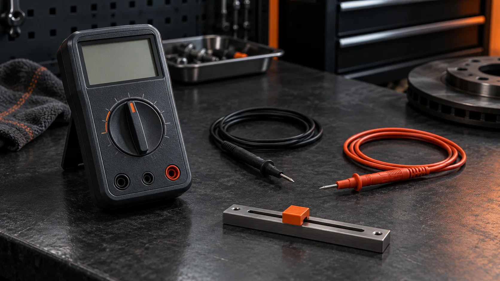
“The wire beeps” is an incomplete repair-order note. It records a sound without identifying the meter setting, measured path or vehicle acceptance criterion. Before using that observation to clear a circuit, find out what caused the meter to sound.
A continuity beep reports that the meter's continuity condition was met. It is not a universal automotive resistance specification. The practical task is to preserve the numeric observation and compare it with the correct procedure.
The sound belongs to the instrument
Continuity functions use a resistance threshold to produce an audible indication. Thresholds depend on the instrument; some meters allow the user to select one. A setting remembered from another meter is not a reliable substitute for checking the current manual and configuration.
A beep therefore does not mean exactly zero ohms. Likewise, silence alone does not establish an open circuit. A resistance can be above the sound threshold while still producing a finite reading. Read the display, units and function together, and consult the manual for indications such as OL.
Keep two questions separate: “Did this meter sound?” and “Does this result meet the vehicle test requirement?” Only the second supports the procedure's pass/fail decision.
Establish a valid test before interpreting it
Use continuity only on a de-energized circuit, following the vehicle and meter procedures for isolation and stored energy. Do not assume an ignition-off condition alone establishes a safe test state. Confirm that continuity testing is permitted for the component and exact terminals involved; this article is not a procedure for restraint or high-voltage systems.
Check the meter's function and lead sockets. Verify its response with the leads apart and together as directed by its manual. If those checks are inconsistent, resolve the setup before testing the vehicle. Do not turn an instrument problem into a wiring diagnosis.
Record what was disconnected to define the measured path. Where another path remains connected, the observation may not describe the intended conductor alone. Use the service procedure's isolation requirements rather than disconnecting modules by guesswork.
When two meters disagree
Imagine a fictional bench exercise in which two meters show similar finite resistance, but only one sounds. Before declaring one defective, compare their continuity thresholds and settings. Different sound criteria can explain that observation without a change in the test item.
For a shop handoff, record the following before repeating the test:
- Meter identification and continuity setting or documented threshold.
- Exact test points and circuit isolation state.
- Displayed resistance and units, alongside beep or no beep.
- Lead contact check and whether the reading stayed stable.
- Applicable vehicle procedure and its acceptance criterion.
If the threshold is unknown, write “threshold not verified.” That is more useful than filling the gap with a remembered generic number. Retrieve the meter documentation before treating the sound as a quantitative result.
Choose the next test from the unanswered question
A valid finite reading may answer a continuity question in the prescribed procedure. It does not, by itself, demonstrate circuit behavior at operating load. If the complaint concerns a device failing while operating, follow the approved diagnostic sequence to evaluate that condition. The guide to voltage drop versus resistance testing explains that separate decision.
If a reading changes when the test is repeated, document what changed: test points, contact, isolation, meter setting or the condition under investigation. Avoid calling the result an intermittent harness fault until the test setup and applicable procedure support that conclusion.
If the display is out of range or the setup check fails, resolve that limitation first. A silent buzzer is too little evidence to authorize replacing a harness or component.
Replace a vague note with a usable record
Instead of “wire good, beeps,” use a note such as: “Specified path tested in the isolation state required by procedure X. Meter and continuity setting recorded. Numeric reading and sound result attached. Compare with the procedure's limit; operating-load behavior has not been evaluated.”
This is an example of documentation structure, not a claim about a real vehicle. Add the actual reading and procedure reference from the job. The downloadable continuity record provides those fields without inventing a universal acceptance limit.
Carry evidence into the diagnostic decision
The useful result is a defined test with a recorded observation and a clear limit on what it establishes. A sound can help locate a path quickly; the technician still has to interpret the measurement in the vehicle's diagnostic procedure.
Shops considering STEP can use the same discipline when discussing a case: retain the test conditions, evidence and remaining question. Request STEP Early Access to discuss your shop's diagnostic workflow.