
Mechanic Guides
Automotive Oscilloscope Cursor Measurements: Define the Endpoints First
Make automotive scope cursor measurements repeatable with defined endpoints, channel, units and capture context. Includes a downloadable measurement record.
Published · 4 min read
Quick answer
Define both waveform endpoints, the channel and units before recording a cursor difference. Keep the original capture and placement convention so another technician can repeat the measurement.
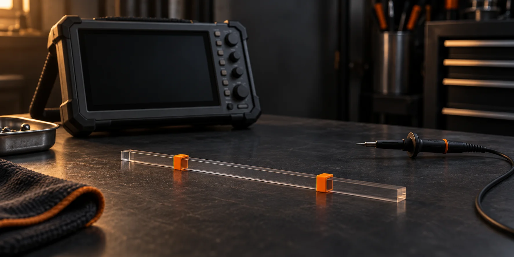
Two technicians can open the same automotive waveform and report different intervals without either misreading the digits. They may have placed their cursors on different features. A useful measurement starts with a definition of its endpoints, then preserves enough context for someone else to repeat it.
This guide is for reviewing captured scope data. It does not specify vehicle connections, acceptable pulse widths or timing limits; those come from the applicable test procedure.
Decide what the interval means
Before dragging a cursor, finish this sentence: "I am measuring from ___ to ___ to answer ___." Naming both features prevents a convenient pair of visible edges from becoming an unexplained diagnostic result.
For example, measuring the duration of one pulse requires a start and finish on that pulse. Measuring repetition requires equivalent points on successive cycles. Those are different questions even if the displayed values look similar.
Write down the endpoint convention used by the applicable procedure. If it does not define one, state your convention explicitly and treat the result as an observation, not an OEM pass/fail measurement. A visual estimate near an indistinct edge should remain identified as an estimate.
Read the axis before the number
In a normal time-domain scope view, vertical cursors mark time positions; horizontal cursors mark positions on a signal axis. Other views can use different axes. Read the units and associated channel rather than assuming every cursor pair measures milliseconds or volts.
A pair can show two absolute positions and their difference. Record which result you used. A difference in signal level is not automatically the signal's absolute maximum, and a time position relative to the display origin is not automatically a pulse duration.
Some software also displays the reciprocal of a selected time interval as an equivalent frequency. That conversion alone does not establish that your chosen interval represents one repeating cycle. Label the physical event first.
Make the placement repeatable
Use this review sequence on the saved capture:
- Identify the channel, signal name and units. Include the original capture filename so the result remains connected to its evidence.
- Find the event in the full record, then inspect its detail. Keep enough surrounding context to distinguish it from neighboring events.
- Place the first cursor using your stated start convention. Place the second using the stated finish convention.
- Record the two positions, their difference and the convention together. Preserve a view showing both endpoints.
- Ask whether another technician could select the same features from your description. If the answer depends on guessing, improve the description before comparing values.
For the distinction between a closer view and a new acquisition, see timebase versus zoom. More visible detail is useful only when the underlying capture supports the question.
Reconcile cursors with automatic measurements
Scope software can calculate characteristics such as minimum, maximum, frequency and pulse width. A cursor interval and an automatic result are not necessarily the same measurement. Check the selected channel, measurement definition and region in your instrument's documentation before treating a disagreement as a fault.
PicoScope, for example, can use rulers in conjunction with measurements. Preserve those settings when sharing a result. "Pulse width" without the relevant setup may leave the next technician unable to reproduce your number.
Do not choose whichever result better fits the suspected failure. First establish whether both methods evaluated the same feature under the same definition. If that remains unclear, report the disagreement and the missing information.
A fictional shop handoff
A technician sends a cropped image with "interval longer than reference." The receiving technician cannot tell which two edges were selected or whether the reference used the same endpoints.
A better handoff names the capture, channel and operating condition, describes each selected feature, and attaches the endpoint view alongside the full record. It also states that comparison against the applicable procedure is still pending. No component verdict is implied by this fictional example.
Keep a measurement record
Use the downloadable endpoint record to preserve the question, endpoint definitions, values, units, capture location and unresolved limitations. For a before-and-after comparison, fill out the same fields for both captures instead of saving only the two final numbers.
The practical outcome is a result another mechanic can inspect and challenge. Explore STEP Early Access if structured diagnostic work is relevant to your shop.