
Mechanic Guides
Connector Views: Confirm Terminal Side and Wire Side Before Probing
A practical connector-identification check for mechanics: confirm the diagram viewpoint, connector half and cavity before trusting an electrical measurement.
Published · 5 min read
Quick answer
Read the manual legend before assigning a cavity. Match the exact connector, illustrated half and viewing direction using physical landmarks. If the diagram, housing marks and wiring disagree, resolve the mismatch before probing or moving a terminal.
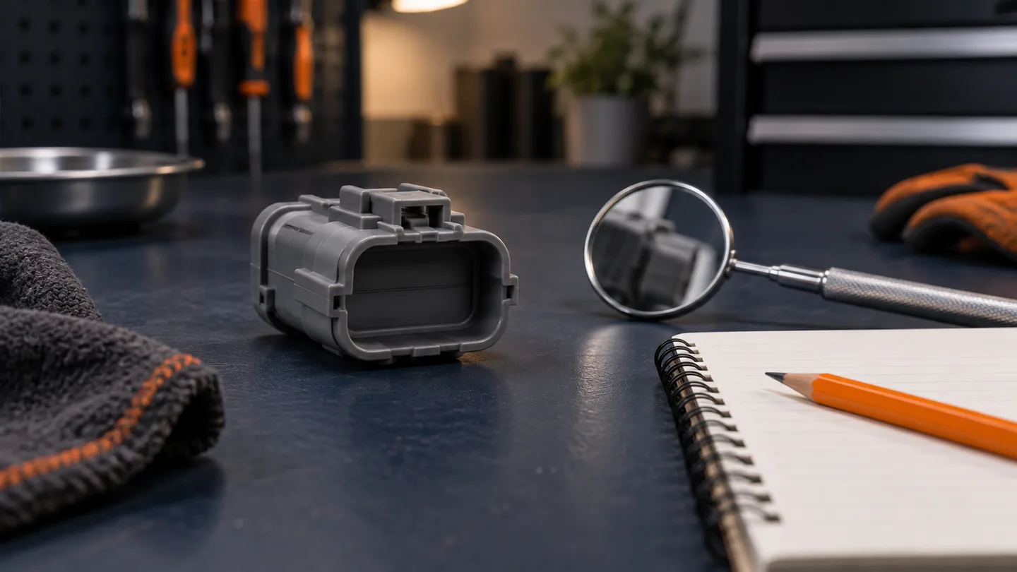
A voltage reading can be accurate and still answer the wrong question if the probe is in the wrong cavity. Before an electrical test, establish which physical connector and viewpoint the drawing represents.
Do not begin with a remembered rule such as “all diagrams show the terminal face.” Begin with the legend for the service information in front of you, then reconcile it with the connector on the vehicle.
Separate the connector half from the viewing direction
Two questions belong in the record: which half of the connection is illustrated, and from which direction is it shown? A label identifying the harness connector does not, by itself, tell you whether you are looking toward its mating face or toward its wire entry.
Mitsubishi's historical January-February 2021 Tech Talk, page 2, explains different conventions for device connections, intermediate connectors and other connector types. It also describes a case where housing terminal numbering conflicts with service information. The lesson is to consult the applicable legend and resolve conflicts, not to import that publication's conventions into another manufacturer's diagram.
Establish identity before orientation
Confirm the vehicle configuration, component and connector reference. Then compare the cavity arrangement, latch, keying features and relevant wire information with the applicable documentation.
A matching shell alone is insufficient. Subaru's historical October 2022 technical newsletter, page 12, warns that physically identical connectors can serve different components and carry different circuits. That is a reason to preserve connector identity during disassembly, not a pinout for the vehicle in your bay.
If previous repairs have changed the harness, record that evidence. Do not force a match by choosing whichever drawing looks closest.
Use a short identification record
Before selecting a test cavity, write down:
- The service-information reference, revision and vehicle applicability.
- The connector ID and component or junction it belongs to.
- The exact viewpoint wording and its meaning under that manual's legend.
- Which connector half is shown and which half you are holding.
- The physical landmarks used to orient the drawing.
- The intended cavity, circuit designation and documented wire information.
Treat wire color as supporting evidence alongside the rest of the identification. If a physical mark or wire detail disagrees, pause and resolve it using applicable service information or technical support. Do not silently renumber the drawing.
Photograph the view without inventing a pinout
An original shop photograph can help a coworker repeat the identification. Keep the latch or another distinctive landmark visible and describe the camera direction in the note. Preserve the original image; add any proposed cavity label to a separate annotated copy.
Distinguish what the photo actually shows from what the diagram establishes. A cavity hidden by the housing or wiring should remain unconfirmed until it can be identified correctly. Do not use a generated illustration as evidence for terminal numbering.
Identification is not permission to probe
After confirming the cavity, follow the prescribed test method, circuit state and terminal-access instructions. Use suitable adapters and avoid damaging contacts or seals. Do not bridge cavities or apply power as an orientation check.
Restraint, high-voltage and other protected circuits require their own service precautions and permitted test equipment. This guide is a documentation check; it does not authorize a generic resistance test or backprobe procedure on those circuits.
For an ordinary circuit where testing is permitted, the choice between voltage-drop and resistance testing is a separate decision from connector identification.
Fictional example: two technicians, two viewpoints
An imagined technician hands over a case with a connector photograph but no viewing-direction note. The next technician sees the same latch feature yet is holding the opposite half of the connection.
Before testing, they retrieve the legend, confirm the illustrated half and document the intended cavity together. No new voltage result is recorded until that identification is settled. This example illustrates a handoff problem; it supplies no real vehicle pin numbers or wiring instructions.
Make the measurement traceable
Attach the identification record to the measured value, units and test conditions. “Voltage at connector X, cavity confirmed under the cited view” is more useful than a number beside an unlabeled photo.
Use the worksheet with the diagnostic report template. Mechanics interested in STEP's developing diagnostic workflow can request early access.