
Mechanic Guides
Intermittent Electrical Fault Diagnosis: Build a Capture Plan Before Replacing Parts
A practical capture plan and downloadable diagnostic event log for repair shops investigating intermittent electrical faults.
Published · 7 min read
Quick answer
Intermittent electrical fault diagnosis starts with a capture plan: define the failure condition, preserve existing evidence, and choose a measurement that can distinguish the suspected causes while the fault is present.
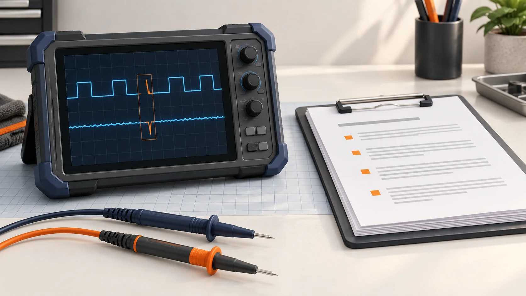
The vehicle works during your first inspection. The customer describes a brief shutdown or an accessory that stops responding, but the scan report does not explain what happened. You now have two jobs: investigate the circuit and make sure the next occurrence produces usable evidence.
For an independent repair shop, that second job matters when the vehicle stays overnight, a different technician takes over, or the customer returns weeks later. “Checked wiring, seems OK” gives the next person almost nothing to continue from.
This guide provides a way to organize that work, including a reusable diagnostic event log. It addresses ordinary automotive low-voltage diagnostic planning. Exact connections, limits and procedures must come from the applicable vehicle and test-equipment instructions.
1. Turn the complaint into an event you can recognize
Write down what changed, how the driver noticed it, and what happened immediately before and after. Separate the customer's description from your own observations.
Ask questions that change the capture plan:
- Does the concern occur during starting, steady operation, or a transition between states?
- What accessories were operating, and what else stopped working at the same moment?
- Did the concern follow a soak period, temperature change, vibration or wet conditions?
- Did it recover on its own, after a key cycle, or after someone disturbed a connector?
- What recent repairs or added electrical equipment may affect the investigation?
These are leads, not diagnoses. “It happens after rain” does not prove water intrusion. Record that relationship as reported until you can reproduce or otherwise substantiate it.
Choose an observable event before setting up equipment. “Electrical problem” is too broad. “The accessory stops responding while its command remains active” is a question you can investigate.
2. Preserve the starting evidence
Save the initial scan report, code status and available failure records before clearing anything. Note which modules were scanned and any limitations of the equipment or coverage.
Freeze-frame information can help identify operating conditions when an emissions-related DTC was recorded. It is not necessarily a recording of the instant the underlying fault began, and code clearing can erase it. Availability and content depend on the vehicle and system. The Snap-on MICROSCAN manual explains these limits in its OBD freeze-frame section.
Keep original files alongside your interpretation. If you later decide a recorded code was incidental, preserve the original scan and explain why your diagnostic direction changed.
3. Write the question each measurement must answer
Before connecting equipment, complete this sentence: “If this suspected cause is present, I expect to observe ___ under ___ conditions.”
That sentence prevents a collection of unrelated screenshots from becoming the diagnostic record. A useful test has a defined question, relevant conditions, a documented connection and a reason for the next action.
For example, if an accessory stops operating, your question might concern its command, power supply or ground path. Choose the next measurement from the applicable wiring diagram and diagnostic procedure. Do not infer connector identity or circuit behavior from wire color alone.
A result also has a boundary. A circuit behaving normally while the symptom is absent does not demonstrate what happened during the reported failure. Write “not reproduced during this test” when that is what you actually established.
4. Choose a capture method that fits the event
A static reading can answer a steady-state question. A brief dropout requires equipment and settings capable of recording the event you are looking for.
An oscilloscope trigger can retain a capture when a selected signal meets defined conditions. It can also help compare the timing of several measured signals. Pico's trigger documentation explains the relationship between trigger conditions and the captured waveform.
Set up from the expected circuit behavior and the equipment instructions. Document the selected channels, connection points, ranges and capture settings. Avoid taking an unexplained trigger threshold from an unrelated example.
Check that the recording will be retained. Some equipment can stop or save automatically after a configured event; Pico describes this in its Events and Actions training. Confirm the capabilities and setup of the tool you are actually using.
5. Test the circuit under relevant conditions
An apparently sound connection can still require an electrical test. Fluke's automotive voltage-drop guidance explains why visual inspection alone can miss a restriction and why the ground path matters.
Use the required operating load and test points when the applicable procedure calls for voltage-drop testing. Record the condition with the result. A value without the circuit state, connection points and applicable limit is difficult for another technician to interpret.
If a controlled harness or connector inspection is appropriate, monitor the relevant signal while following the manufacturer's method. Do not pull on wiring, damage terminals, pierce sealed circuits indiscriminately or improvise load tests on sensitive circuits.
This workflow does not authorize probing airbag or restraint circuits, high-voltage systems, or any circuit requiring special isolation. Follow the relevant training and service precautions. During a permitted road test, secure equipment and use logging or a second qualified person; the driver must stay focused on driving.
6. Keep a diagnostic event log another technician can use
Use one entry for each meaningful test or captured event. The following is an original documentation template, not an OEM procedure.
- Case and vehicle: repair-order reference, confirmed vehicle configuration and technician.
- Concern: customer report and the symptom you are attempting to observe.
- Conditions: operating state, relevant environmental conditions and active loads.
- Question: the hypothesis this particular test is intended to evaluate.
- Source and setup: applicable procedure, test points, equipment and capture settings.
- Observation: what was actually measured or seen, with units where relevant.
- Evidence: saved scan, waveform or photograph filename and timestamp.
- Interpretation: what the result supports, what it does not establish, and the next check.
- Verification status: original event reproduced, repair performed, and conditions retested.
The separation between observation and interpretation is essential. It allows another technician to challenge the conclusion without losing the measurement.
For example, “bad connection” is a conclusion. A more useful note identifies the affected function, what was being monitored, the recorded change, whether the symptom occurred at the same time, and which inspection or test will localize the problem next. A captured dropout does not, by itself, identify a specific terminal or component.
Download the diagnostic event log and adapt it to your shop's case records.
7. Close the original diagnostic question
After a supported repair, repeat the relevant verification procedure and record what happened under the original failure conditions, where those conditions can be reproduced safely.
State the outcome precisely. “The symptom did not recur during the documented test” is different from “all possible operating conditions were verified.” If the original event has not been reproduced, retain that limitation and define the next capture or follow-up plan.
Do not close an intermittent case solely because codes were cleared or the vehicle completed an uneventful idle period. The final record should connect the complaint, evidence, demonstrated fault, repair and verification.
Keep the next test connected to the case
A useful diagnostic workflow preserves the reason for each test and the result that changed the plan. That is the workflow STEP is being built to support for professional mechanics: vehicle context, source references, completed checks and a clear next step.
If your shop regularly loses diagnostic context between notes, tools and people, see STEP for mechanics or request early access. Bring a real workflow problem you want the product to help organize.