What this code means
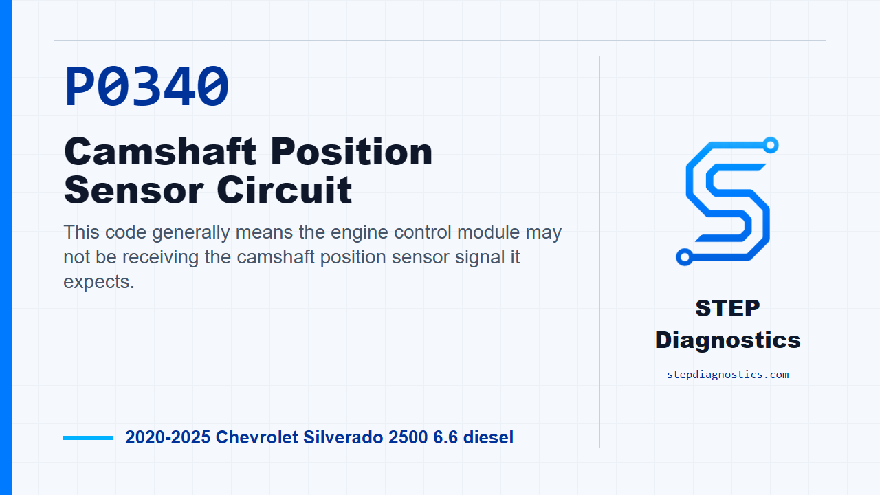
This code generally means the engine control module may not be receiving the camshaft position sensor signal it expects.
What the vehicle may do
- The vehicle may have an extended crank during startup.
- The engine may run normally at times if the fault is intermittent.
- A warning light or stored fault may be present.
Possible fault areas
- A possible issue in the camshaft position sensor signal circuit.
- A possible reference or low-reference circuit problem.
- A possible wiring, terminal, or connector concern between the sensor and control module.
- A possible control module side circuit issue.
- A possible mechanical signal issue around the sensor, reluctor, oil condition, timing drive, or tensioner.
Diagnostic path
Opening: what this code is telling you
This camshaft position sensor circuit code means the engine control module may not be seeing the cam signal it expects. On this truck, that may show up as an extended crank on startup, or it may act like an intermittent signal problem. Broadly, think in terms of the cam sensor circuit, the 5 V reference and low-reference sides, the signal wire, connector or terminal problems, the control module side of the circuit, and possible mechanical signal problems around the reluctor and timing drive. The cam reluctor has 4 teeth on the edge of the camshaft position reluctor ring mounted on the camshaft. For P0340, the diagnostic is watching for a missing cam signal or too few cam pulses. It can set when the Camshaft Position Sensor equals No Signal — For greater than 5.5 s; No Signal — For greater than 4 s — Starter is engaged; Less than 4 pulse(s) — For greater than 3 s; No Signal — During the first 2 engine revolutions; or No Signal — During 200 engine revolution(s). Treat the running conditions as monitor gates: the related airflow and crank sync conditions need to be clean, and one gate includes MAF Sensor = Greater than 2.0 g/s.
Start with verification before circuit testing
Start with the basic system checks, then follow a structured diagnostic approach, and have the diagnostic game plan clear before you start branching. With ignition on and the vehicle in service mode, make sure there is not an active reference fault that could affect this circuit. If that kind of fault is present, check what it means first. If the reference side is not setting a fault, run the engine and check whether the companion cam performance fault is active. If it is, move into the circuit testing. If it is not, watch the scan tool Camshaft Position Active Counter. For this path, it should increment. If the counter does not increment, go into circuit testing. If it does increment, wiggle the harness and connectors at the B23 Camshaft Position Sensor and the K20 Engine Control Module while watching that counter. If the counter drops out or stops incrementing during the wiggle test, repair the wiring, terminals, or connectors as needed. If the counter keeps incrementing, reproduce the operating conditions for the code, or reproduce the captured conditions from the failure data, then verify the code does not reset. If it does reset, continue into circuit testing. If it does not reset, the result is All OK.
Low reference circuit check
For circuit testing, turn ignition, vehicle power, and all vehicle systems off, then disconnect the B23 Camshaft Position Sensor connector. Keep in mind it may take up to 2 min for all vehicle systems to power down before an accurate ground or low reference circuit continuity test can be performed. First test between low reference circuit terminal 2 and ground. You want less than 10 Ω. If that test is 10 Ω or greater, disconnect the K20 Engine Control Module connector and test continuity from low reference terminal 2 at the component harness to the other end of that circuit at the control module harness. That circuit should be less than 2 Ω. If it is 2 Ω or greater, repair the open or high resistance in the low reference circuit. If it is less than 2 Ω, the path calls for replacing the K20 Engine Control Module.
5 V reference circuit check
If the low reference test from terminal 2 to ground is less than 10 Ω, turn ignition on with the vehicle in service mode and check the 5 V reference circuit. Test between terminal 1 and ground. The expected range is 4.8 to 5.2 V. If terminal 1 is less than 4.8 V, turn ignition and vehicle power off, disconnect the K20 Engine Control Module connector, and test terminal 1 at the component harness to ground for infinite resistance. If it is less than infinite resistance, repair the short to ground on the 5 V reference circuit. If resistance is infinite, check continuity from terminal 1 at the component harness to the other end of the circuit at the control module harness. That should be less than 2 Ω. If it is 2 Ω or greater, repair the open or high resistance. If it is less than 2 Ω, replace the K20 Engine Control Module. If the 5 V reference at terminal 1 is greater than 5.2 V, turn ignition and vehicle power off, disconnect the K20 Engine Control Module connector, then turn ignition back on with the vehicle in service mode. Test terminal 1 at the component harness to ground. It should be less than 1 V. If it is 1 V or greater, repair the short to voltage. If it is less than 1 V, replace the K20 Engine Control Module.
Signal circuit check
If the 5 V reference circuit is in range, move to the signal circuit. Test between signal circuit terminal 3 and ground. The expected range is also 4.8 to 5.2 V. If terminal 3 is less than 4.8 V, turn ignition and vehicle power off, disconnect the K20 Engine Control Module connector, and test terminal 3 at the component harness to ground for infinite resistance. If it is less than infinite resistance, repair the short to ground on the signal circuit. If resistance is infinite, check continuity from terminal 3 at the component harness to the other end of that circuit at the control module harness. It should be less than 2 Ω. If it is 2 Ω or greater, repair the open or high resistance in the signal circuit. If it is less than 2 Ω, replace the K20 Engine Control Module. If signal circuit terminal 3 is greater than 5.2 V, turn ignition and vehicle power off, disconnect the K20 Engine Control Module connector, then turn ignition back on with the vehicle in service mode. Test terminal 3 at the component harness to ground. It should be less than 1 V. If it is 1 V or greater, repair the short to voltage. If it is less than 1 V, replace the K20 Engine Control Module.
When the circuits test normal
Once the low reference, 5 V reference, and signal circuit checks are normal, look at whether the companion cam performance fault is setting. If it is, check the mechanical signal path in one pass: sensor and reluctor play, foreign material, air gap, sensor installation, looseness, visible damage, dirty or contaminated oil, and timing-drive or tensioner wear or damage. If one of those conditions exists, repair or replace as necessary. If those checks are normal, test or replace the B23 Camshaft Position Sensor. If the companion cam performance fault is not setting after the circuit checks, the path also ends with testing or replacing the B23 Camshaft Position Sensor.
Repair verification and takeaway
After the repair is completed, keep verification separate from the category-specific testing. Verify the repair and confirm the code stays gone under the correct operating conditions. The takeaway is simple: do not jump straight to the cam sensor. Prove the low reference, 5 V reference circuit, signal circuit, connector integrity, and mechanical signal path first, then finish with a clean verification. For more diagnostic training, visit stepdiagnostics.com.
Final check
This code is often best handled as an electrical signal diagnosis first, with mechanical signal checks after the circuit path is proven.
For more guided automotive diagnostics, visit STEP Diagnostics.