What this code means
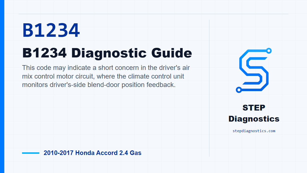
This code may indicate a short concern in the driver's air mix control motor circuit, where the climate control unit monitors driver's-side blend-door position feedback.
What the vehicle may do
- The driver side temperature control may be incorrect or inconsistent.
- The air mix door may not respond normally to temperature commands.
- The climate control system may store the code again after clearing if the fault is currently present.
Possible fault areas
- Possible wiring trouble between the climate control unit and the driver's air mix control motor.
- Possible issue on the reference-voltage, sensor common, or position signal side of the circuit.
- Possible driver's air mix control motor concern.
- Possible climate control unit concern.
Diagnostic path
Set up the diagnosis
For this Accord, B1234 points to a short concern in the driver's air mix control motor circuit. In plain terms, the climate control unit may not be seeing the driver's blend door position circuit the way it expects. The driver side temperature control may be incorrect, inconsistent, or may not respond normally. Broadly, this can involve the wiring between the climate control unit and the driver's air mix motor, the power (5 V) circuit, the sensor common side, the position signal side, the motor assembly, or possibly the climate control unit. If other short-circuit codes are present at the same time, do not ignore them; there may be an open or a short to body ground in that shared power circuit, so sort that context out before narrowing everything to this one branch.
Verify B1234 before circuit testing
Start by verifying the problem. Clear the code with the HDS. Then turn the ignition to LOCK (0) and back to ON (II), or use the engine start/stop button to go from OFF mode back to ON mode. Run the self-diagnostic function with the HDS or with the climate control unit, then check for codes again. If B1234, or 41, comes right back, continue into the circuit checks. If it does not come back, treat it as an intermittent fault and inspect for loose wires or poor connections in the driver's air mix control motor circuit.
Check the S5V line for an open
With the ignition in LOCK (0), or OFF mode, disconnect the climate control unit 32P connector and the driver's air mix control motor 7P connector. Check continuity on the S 5V, or S5V, line between the climate control unit 32P connector No. 24, black wire, and the driver's air mix control motor 7P connector No. 3, black wire. If you have continuity, that feed circuit is not open, so move on. If there is no continuity, repair the open in the wire between the climate control unit and the driver's air mix control motor.
Check for shorts on the position signal circuit
Keep the connectors disconnected and the ignition off. Now check whether the AMD-P driver position line is shorted to the sensor common line. Check continuity between the climate control unit 32P connector No. 10, gray wire, and No. 22, blue wire. If there is continuity, repair the short in the wiring between the climate control unit and the driver's air mix control motor. If there is no continuity, that pair is not shorted together, so continue to the ground-short check. Next check the AMD-P driver line to body ground, using climate control unit 32P connector No. 10, gray wire, to body ground. If you have continuity there, repair the short to body ground in the wire between the climate control unit and the driver's air mix control motor. If there is no continuity, the AMD-P driver line checks OK, and you can move to the motor resistance checks.
Check the motor internal resistance
With the ignition still in LOCK (0), or OFF mode, and with both the climate control unit 32P connector and the driver's air mix control motor 7P connector disconnected, measure resistance inside the driver's air mix control motor between terminal No. 1 and terminal No. 3. The expected resistance is 6 kΩ±1.8 kΩ. If the resistance is not 6 kΩ±1.8 kΩ, replace the driver's air mix control motor. If it is within that value, continue to the sweep check.
Check the motor position signal through its travel
Reconnect the driver's air mix control motor 7P connector, but leave the climate control unit 32P connector disconnected. Use a 12 V power source and ground at the motor drive circuit through the climate control connector: terminal A is climate control unit 32P connector No. 2, pink wire, and terminal B is No. 3, light blue wire. Apply power and ground, then reverse the connections to drive the motor the other way. Be careful here: applying power and ground incorrectly can damage the motor. Follow the terminal setup carefully, and when the motor stops running, disconnect battery power immediately. While doing this check, measure resistance between climate control unit 32P connector No. 10, gray wire, and No. 22, blue wire. The resistance should change between about 0-6 kΩ±1.8 kΩ. One detail to watch: continuity between AMD-P driver and sensor common may disappear when the motor is turned all the way to the stop, and normally the climate control unit does not drive the motor to the stop. If the resistance changes between about 0-6 kΩ±1.8 kΩ, replace the climate control unit. If it does not change through that range, replace the driver's air mix control motor.
Takeaway
The clean way through B1234 is to prove the code is current, check the S5V feed for an open, check the position signal for shorts to sensor common and ground, then judge the motor by its fixed resistance and sweep response before condemning the control unit. For more diagnostic training, visit stepdiagnostics.com.
Final check
Work the circuit in order: verify the code, prove the wiring, check the motor response, then make the control-unit decision only after the circuit and motor behavior are known.
For more guided automotive diagnostics, visit STEP Diagnostics.