A weak air-conditioning complaint and an A/C pressure-sensor circuit code are not the same diagnosis. On the Honda Accord 2.4 gas engine, the control module uses an electrical signal representing refrigerant pressure. The signal, its supporting circuits and the refrigerant system must be evaluated as related but separate parts of the evidence.
This educational overview covers the 2010–2017 Honda Accord 2.4 gas profile. Sources at the first and last years support the functional explanation, not identical equipment, refrigerant specifications, connector assignments, calibrations or procedures for every build. Confirm the exact vehicle and A/C configuration. Its applicable service information controls diagnostic limits, test connections, service equipment, refrigerant handling and repair verification.
What the pressure sensor contributes
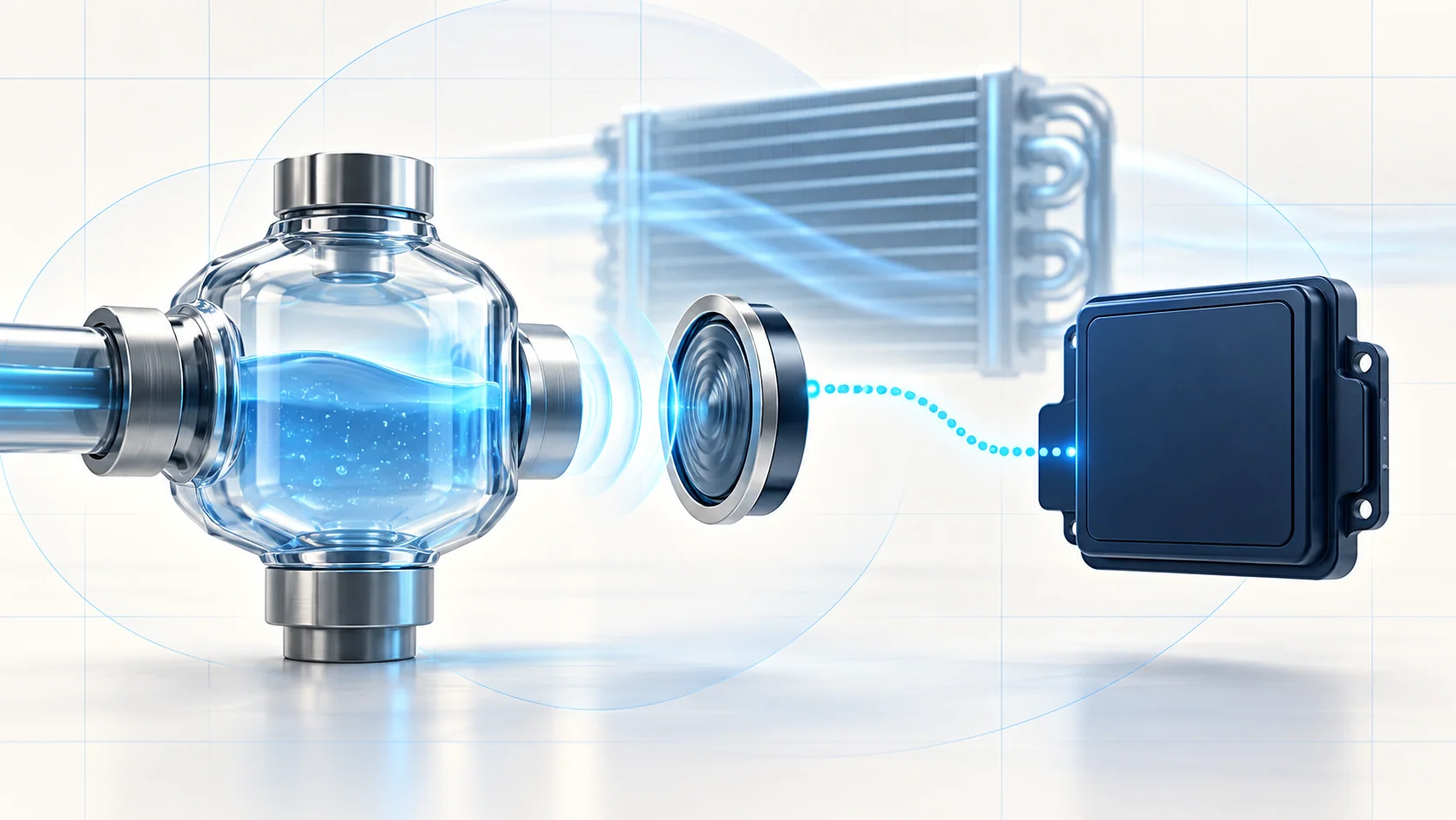
The A/C pressure sensor converts changes in refrigerant pressure into an electrical input for the engine control module or powertrain control module. In the endpoint descriptions examined, lower pressure corresponds to a lower output voltage and higher pressure to a higher output voltage. The module compares the input with the behavior expected by its diagnostic strategy.
That relationship does not make every low voltage a valid low-pressure measurement. A damaged signal wire, missing reference supply, poor return path or sensor fault can produce an electrical value that does not represent the refrigerant system correctly. A scan-tool value is an interpretation of the input, not an independent pressure measurement.
Pressure information belongs to the A/C control system, but an accepted pressure signal alone does not prove normal cooling. Refrigerant condition, heat exchange, compressor operation, airflow and cabin-side controls still have their own diagnostic paths. This article does not specify a compressor enable threshold or establish that one particular protection response occurs on every configuration.
Two codes, two electrical directions
| STEP guide | What it helps investigate | What it does not prove by itself |
|---|---|---|
| P0532 — A/C pressure sensor circuit low voltage | An input below the applicable electrical diagnostic limit and the sensor, supply, signal or connection paths that can cause it. | Low refrigerant charge, a refrigerant leak or a failed sensor. |
| P0533 — A/C pressure sensor circuit high voltage | An input above the applicable electrical diagnostic limit and the circuit isolation needed to locate the cause. | Excess refrigerant charge, actual excessive pressure or a failed compressor. |
The linked guides are diagnostic context, not universal wiring instructions. Their exact voltages, terminal numbers, wire colors, jumper arrangements and module procedures must be checked against the vehicle being repaired. Do not transfer a connection test from one year or engine to another just because the DTC name is the same.
Failure categories and possible symptoms
The customer may report poor cooling or A/C operation that is not normal. The fault may also be intermittent or primarily visible as a stored code. A complaint can have more than one cause; repairing the circuit fault does not automatically resolve every cooling concern.
- Sensor fault: an incorrect output can misrepresent pressure even when the external circuits are intact.
- Supply or return problem: an open, resistance or connection concern in the supporting path can move the signal outside its expected range.
- Signal-path fault: an open or short can make the module see an abnormal input. The direction and test response must be interpreted using the exact chart.
- Terminal or harness condition: loose terminals, poor contact or disturbed wiring can make a fault appear only under particular conditions.
- Control-module input or software path: consider these only after the applicable circuit checks direct the diagnosis there. A code name is not permission to replace or reprogram a module.
- A separate refrigerant or cooling fault: investigate this through the A/C performance procedure once pressure information is trustworthy, rather than treating the circuit code as a charging instruction.
A disciplined diagnostic approach
- Identify the application and preserve evidence. Record all codes, pending/confirmed status and available captured operating data before clearing anything. Note the A/C complaint, recent work and whether the fault is current or intermittent.
- Reproduce only the prescribed operating state. Use the specified scan data and A/C conditions. If the electrical fault is absent now, investigate connections and intermittent behavior rather than declaring a component good forever.
- Validate the input before judging pressure. Compare the reported signal with the applicable circuit description and diagnostic limits. Establish which parameter is voltage and which, if available, is a calculated pressure. Do not confuse either with an independent measurement.
- Isolate the supported circuit branch. Inspect connector and harness condition, then follow the exact sensor, supply, return and signal tests. A prescribed disconnected-sensor response is evidence within that test, not a general instruction to unplug or bridge arbitrary terminals.
- Separate electrical repair from A/C performance diagnosis. Once the signal path is credible, evaluate any remaining cooling complaint with the correct equipment and performance procedure. Do not add or remove refrigerant merely to make a circuit code disappear.
- Verify the complete repair. Restore connectors and protective routing, exit any diagnostic service mode, and perform module reset or idle learning only where the applicable procedure requires it. Recheck the original signal condition and pending/confirmed codes under the prescribed A/C conditions. Then confirm the original customer complaint separately.
One normal reading or a cleared code is not completed repair verification. An intermittent connection may need further controlled observation even when the first post-repair check is normal.
Repair categories and safety boundaries
The supported repair may be connector or terminal service, wiring repair, sensor replacement or, at the end of a proven diagnostic branch, module-related work. Refrigerant-system repairs belong to a separately supported diagnosis. Use the exact installation, sealing, recovery and final-check requirements; this overview does not establish whether removing a particular sensor opens the refrigerant circuit.
Treat the A/C system as pressurized. Do not loosen a sensor, line or fitting to check for pressure, and do not release refrigerant to the atmosphere. Use the applicable recovery/service equipment and refrigerant identification requirements before opening the system. Never use compressed air to pressure-test the refrigerant system or its service equipment. Avoid breathing refrigerant or lubricant vapor, use the required protective equipment and follow the product and vehicle safety information.
Electrical diagnosis should not defeat pressure protection or force compressor operation. Do not improvise jumpers, supply battery power to sensor circuits or copy terminal assignments from a generic illustration. Use the correct ignition and isolation state for each test, and follow the exact battery-disconnection requirements for replacement work. During running checks, provide exhaust extraction and keep hands, clothing and test leads clear of fans, belts and hot components.
The useful evidence chain is simple: identify the vehicle, prove the signal, isolate the circuit fault, assess actual A/C performance separately, and repeat the relevant checks after repair. P0532 and P0533 describe electrical diagnostic directions, not a refrigerant charge quantity or a replacement-part verdict.