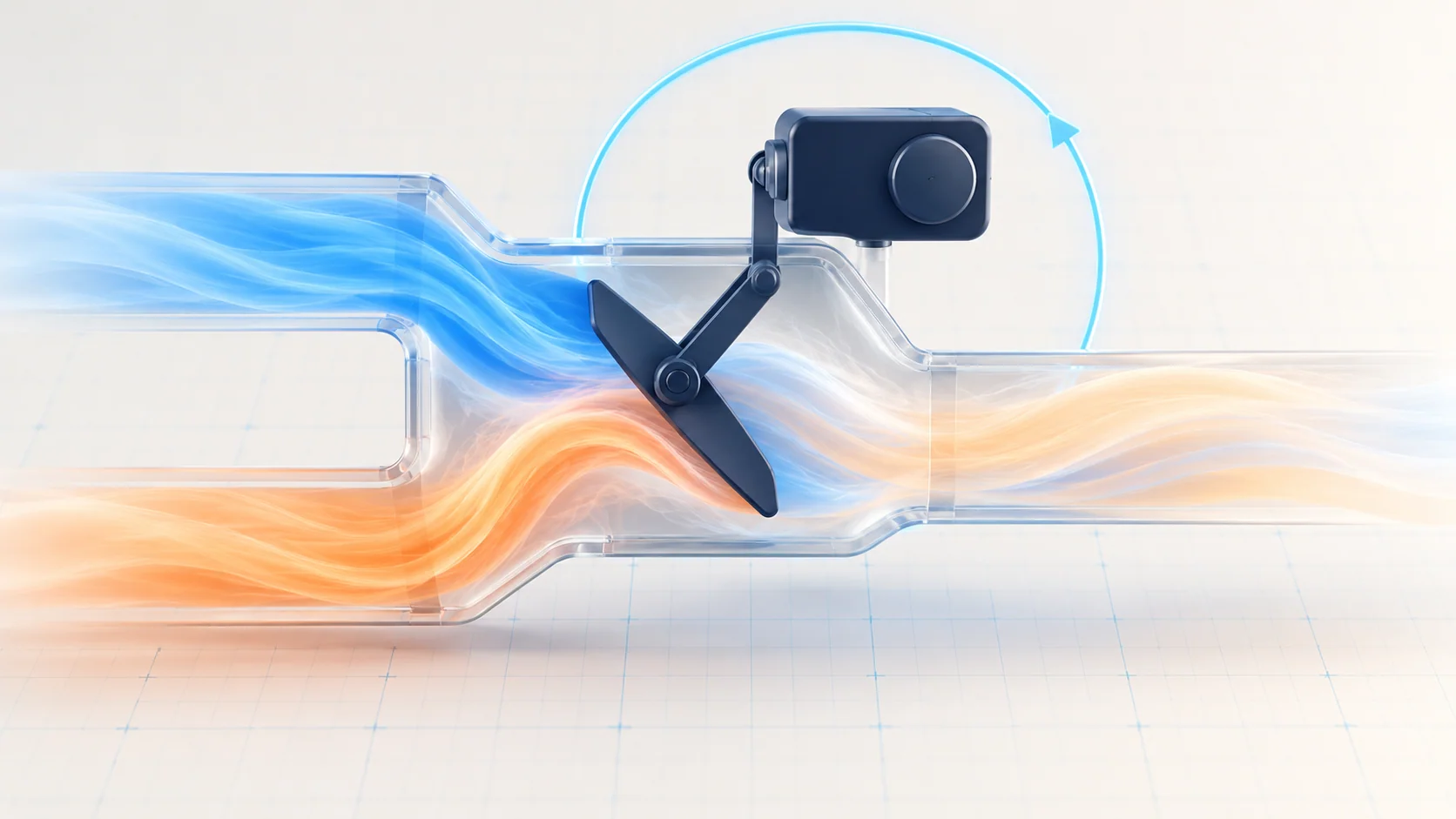
Air-mix control connects a temperature request to a physical change inside the heating and air-conditioning unit. On an equipped Honda Accord 2.4 gas model, an electric actuator moves an air-mix door, while its position feedback helps the climate controller assess the result. A temperature complaint can therefore involve electrical information, motor movement or the mechanical door system. A code does not identify which part to replace by itself.
This educational overview covers the 2010–2017 Honda Accord 2.4 gas vehicle profile. Endpoint sources support the functional explanation, not identical climate equipment, control units, connector assignments or test sequences throughout the range. Confirm the installed manual or automatic system, single- or dual-zone arrangement and relevant equipment options. Passenger-side control applies only where fitted. Use the service information for the exact vehicle for access, electrical tests, component checks and repair verification.
What air-mix control does
The HVAC system must provide a useful outlet temperature, not merely turn a compressor or blower on. At a conceptual level, the air-mix door changes the contribution of heated air to the delivered airflow. Its actuator and linkage translate a temperature-control command into door movement. The controller also needs a credible position signal; a command sent to the motor and a trustworthy indication of position are different pieces of evidence.
Where separate driver and passenger temperature control is installed, identify which side the complaint and DTC describe. Do not assume that both sides share the same failed actuator or that a passenger-side guide applies to a single-zone installation. Equipment-specific climate functions and inputs can affect automatic operation, but this overview does not prescribe a universal sensor or control-unit layout.
Air mix is also distinct from outlet selection and air volume. A mode-door problem changes where air is directed; a blower problem changes its delivery. Refrigerant performance and heater heat availability can affect outlet temperature independently of an air-mix fault. An electrical air-mix code is not a refrigerant-charge measurement, and a warm outlet alone does not prove a defective blend-door actuator.
Three useful diagnostic categories
| STEP guide | What it helps investigate | What it does not prove alone |
|---|---|---|
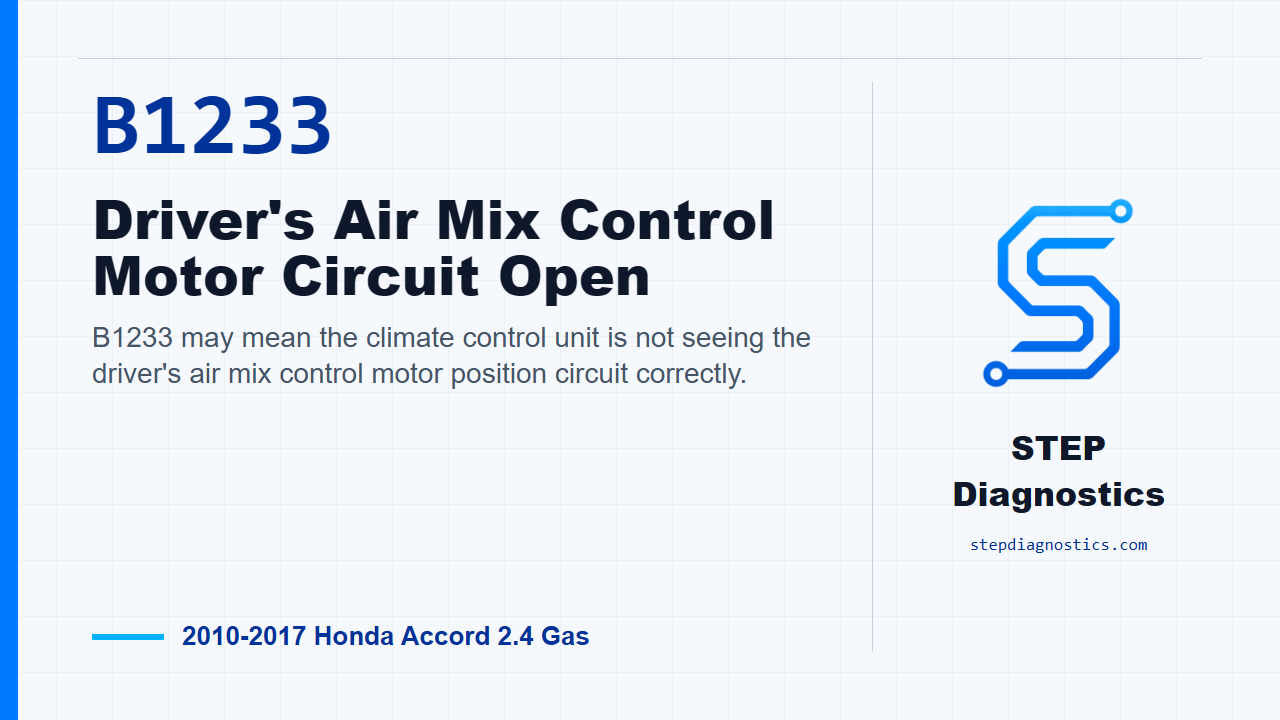
| B1233 — driver air-mix circuit open | The driver-side position-feedback circuit and the applicable signal, common and reference checks | That the motor itself is open or must be replaced |
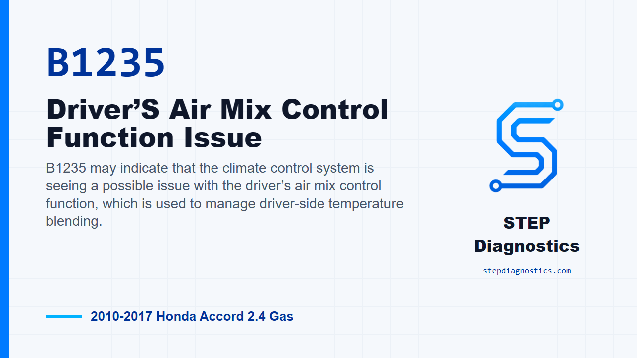
| B1235 — driver air-mix function concern | Driver-side drive circuitry, motor operation, linkage and door movement | That a control command produced the required mechanical travel |
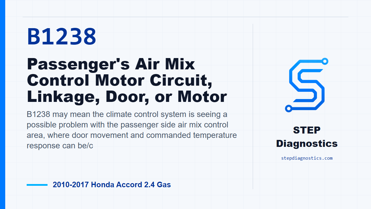
| B1238 — passenger air-mix function concern | The corresponding passenger-side motor, circuit and mechanical path on equipped vehicles | That the driver-side circuit, another actuator or the refrigerant system is the cause |
These guides retain their exact published URLs. The table groups diagnostic questions; it does not make the electrical checks, terminal numbers or component-test order interchangeable between years. In particular, the examined charts do not all place the motor test and wiring checks in the same order. Follow the applicable chart rather than turning this overview into a universal test sequence.
Symptoms and failure categories
The affected side may stay too warm or too cool, respond poorly to a temperature request, or behave intermittently. An equipped dual-zone vehicle may show a side-to-side difference. These are observations to reproduce under controlled conditions, not proof of a particular failed part. Normal operation during one visit does not disprove a stored intermittent event.
Relevant failure categories include an open or short in the specified circuit, poor connector contact, unreliable position feedback, an actuator that does not operate correctly, and a linkage or door that sticks or binds. The climate control unit can remain a diagnostic possibility after the chart's required checks; it is not the starting verdict. A motor can be electrically active without proving that the door moves correctly, while a plausible position signal does not establish correct outlet temperature.
A practical diagnostic approach
- Identify and record. Confirm the climate configuration, affected side, requested setting and observed airflow or temperature behavior. Record HVAC codes and their status before clearing them. An engine-only code reader may not provide the climate-system access needed for this work.
- Separate the complaint from the code. Check whether the problem concerns air temperature, outlet direction or air delivery. Consider heat and cooling availability separately when the symptom requires it; do not rename every temperature problem an air-mix fault.
- Use the correct self-diagnostic and reproduction method. The source procedures distinguish a duplicated fault from an intermittent condition. Follow the specified ignition state and diagnostic method. If the fault does not recur, retain the original evidence and investigate connections rather than declaring a completed repair.
- Follow the exact branch. For a feedback concern, establish the specified signal and shared-circuit integrity. For a movement concern, use the chart's motor, drive-circuit and mechanical checks in its own order. Use the correct disconnected or powered state for each measurement. Do not infer a pinout from another Accord year or another actuator.
- Keep electrical and mechanical evidence separate. Where the applicable component test requires inspection of linkage or door movement, assess that mechanism without forcing it. A failed movement result is not automatically a failed motor; a binding mechanism also needs correction.
- Verify the original behavior after correction. Repeat the prescribed self-diagnostic and code checks, then confirm that the affected temperature control responds under the relevant conditions. A cleared code, one successful sweep or an unplugged actuator is not repair verification. Check for other HVAC faults separately.
Repair categories and safety
Supported repair outcomes may include a directed circuit or connector repair, actuator replacement after testing, or correction of the linkage or door. Control-unit comparison or replacement belongs only to the procedure that establishes that branch, using the correct application and required setup. This article does not specify a universal calibration, reset sequence or replacement-module interchange rule.
Incorrect power and ground application can damage an air-mix motor. Do not apply battery voltage to unidentified terminals or use a generic direct-power test. Follow the exact component procedure, tool and electrical limits; protect terminals from spreading or shorting during probing. Do not take resistance measurements on an energized circuit.
Actuators and linkages can move during a commanded test. Keep fingers and test leads clear, and do not force a door against its stops. Dashboard access can involve restraint-system wiring or components: use the applicable shutdown, isolation and access precautions, and do not probe restraint circuits. Hot coolant and refrigerant circuits are separate hazards; an air-mix complaint is not a reason to open either system. If running checks are required, ventilate exhaust. Do not road-test with inadequate visibility or impaired demisting.
What a useful result establishes
Good diagnosis connects the installed configuration, a reproducible complaint, correctly interpreted feedback, the required motor and circuit checks, and the actual mechanical response. Repair verification must address the original temperature-control concern as well as the relevant codes. Keep the driver/passenger, feedback/movement and electrical/mechanical distinctions intact, and let the exact vehicle procedure decide the next test.