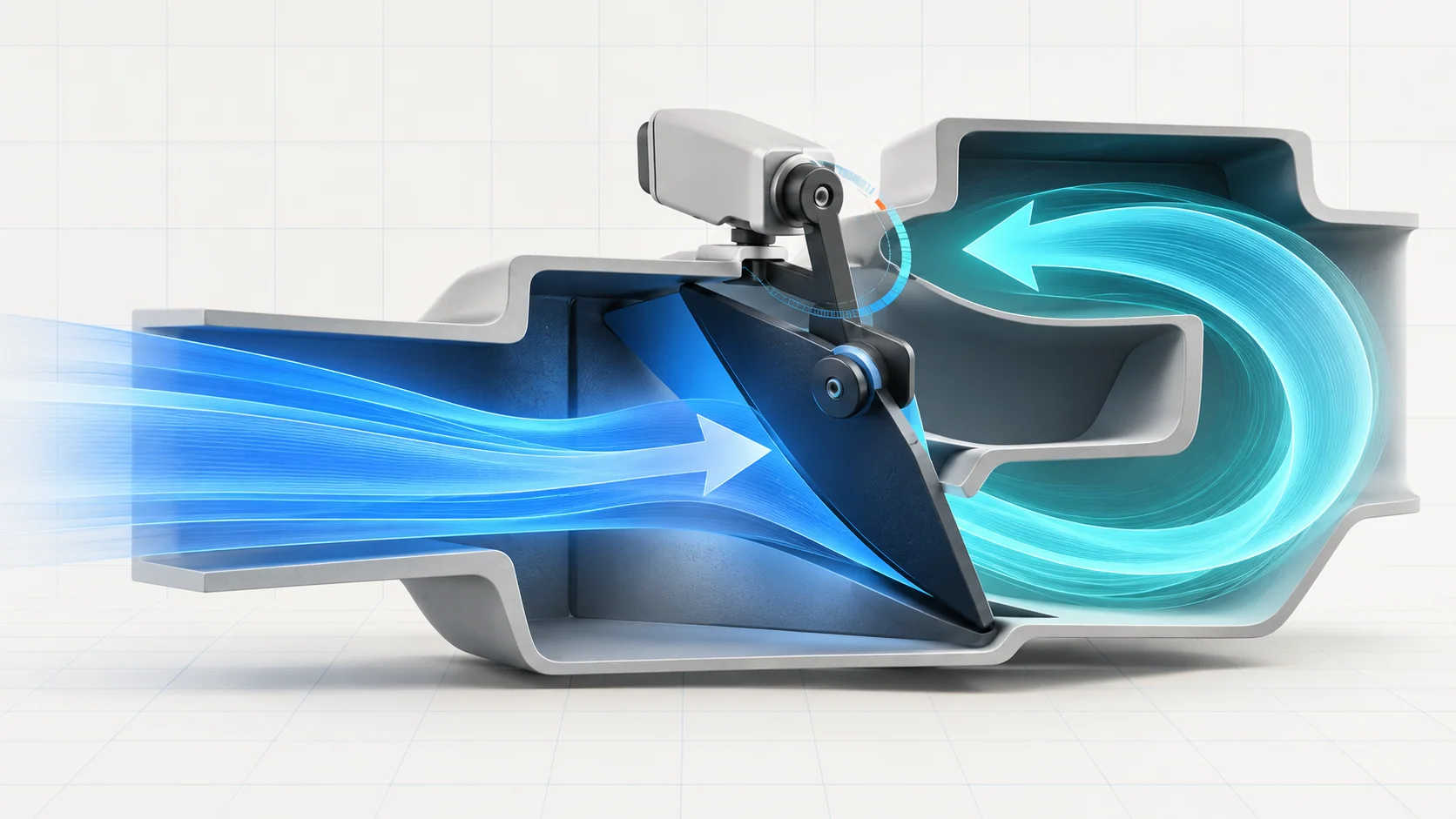
The recirculation door changes where the HVAC system draws its inlet air: from outside the vehicle or from the passenger compartment. Its actuator, linkage and control circuits must work together. A door that will not change position can be an electrical, mechanical or feedback problem, not automatically a failed motor.
This educational overview covers the 2010–2017 Honda Accord 2.4 gas family. Direct source examples are the 2010 Accord L4-2.4L and 2017 Accord Sedan L4-2.4L K24W1. They establish endpoint relevance, not identical climate equipment, wiring or tests for every year. Confirm the exact vehicle and installed climate-control configuration. The applicable service information controls connector identity, commands, resistance limits, access precautions and repair procedures.
What this system controls
Recirculation control selects the inlet-air source. It is different from the air-mix door that regulates temperature and the mode door that selects delivery outlets. A complaint described as “the air door does not work” therefore needs to be narrowed before testing. A recirculation indicator or button request alone is not proof that the inlet door actually moved.
At a functional level, the climate control unit requests movement, the motor drives the mechanism, and position-related information helps the system assess the result. The motor drive path and the feedback path are not the same circuit. An electrical motor test and a check of the door's physical movement also answer different questions.
This is not a refrigeration-pressure diagnosis. Poor cooling by itself does not prove a recirculation fault, and a working inlet door does not prove that the rest of the HVAC system is healthy.
How the two DTC guides fit
The B2983 recirculation circuit, linkage, door or motor guide covers a broad movement/control concern. The 2017 troubleshooting example verifies the fault, checks motor-control wiring for opens and shorts, then proceeds to the motor and mechanical check. The 2010 source likewise identifies the linkage, door and motor-circuit category. Neither source makes the code an automatic motor-replacement instruction.
The B2986 recirculation position/feedback guide leads to a different diagnostic emphasis. In the 2017 source, the OEM chart is titled an open in the recirculation control motor circuit, but it checks feedback and sensor-common wiring, a possible short between reference and feedback, and the motor's internal resistance behavior. Do not read “motor circuit” as meaning only the two drive wires.
The family URLs help readers find the diagnostic category. They do not authorize using one endpoint's exact terminals or test values on every Accord in the title range.
Failure categories and possible symptoms
- Drive-circuit faults: an open, short or poor terminal contact can prevent a valid movement command from reaching the actuator.
- Feedback-circuit faults: a damaged feedback or sensor-common path, an unwanted connection to another circuit, or an internal sensing problem can prevent reliable position information even when the mechanism can move.
- Mechanical restriction: a sticking door or linkage can stop movement. The applicable motor test distinguishes this from an actuator that fails with a freely moving mechanism.
- Control-unit concerns: these belong after the chart's wiring, motor and mechanical checks, not before them.
The driver may notice no change between fresh air and recirculation, inconsistent response, or a door that seems stuck. An intermittent connection may allow normal operation during inspection. Similar HVAC symptoms can come from other functions, so compare the reported concern with the actual inlet-door behavior rather than diagnosing by sound or button illumination alone.
A practical diagnostic strategy
- Identify the function and configuration. Confirm that the complaint concerns inlet-air selection, not temperature mixing, outlet mode or blower output. Use the correct year, engine and climate-control documentation.
- Preserve the initial evidence. Record HVAC codes and the operating circumstances before clearing them. Follow the applicable self-diagnostic and recheck sequence to establish whether the fault is present now. In the source charts, a code that does not return leads toward intermittent-connection investigation rather than immediate component replacement.
- Separate command, movement and feedback. If a supported scan-tool function or the normal controls request a change, observe what actually changes. A moving motor does not prove an intact linkage, and plausible position information does not prove that the door reaches the intended position.
- Prove the appropriate electrical paths. Follow the DTC-specific isolation sequence. Motor-drive wiring, feedback wiring and sensor common require their own checks. Connector condition and terminal fit matter as well as conductor continuity.
- Assess the mechanism and actuator as the chart directs. The 2017 motor test checks for smooth door/linkage movement when the motor does not operate. Do not force a binding mechanism or assume that a new actuator will cure it.
- Make the repair decision from the completed path. Reserve a climate-control-unit decision for the conditions specified after the preceding checks pass. Do not substitute a module simply because the door did not respond.
Continuity testing cannot be improvised on a powered circuit. Likewise, a resistance result taken at a different connector state or mechanical position is not directly comparable with the chart. Obtain the exact applicable procedure whenever those details are uncertain.
Repair categories and verification
Supported repairs may include restoring an open conductor, correcting a short or poor terminal connection, freeing or repairing a linkage/door problem, or replacing a proven faulty actuator. Control-unit replacement is a later chart-directed category, not a default response to either code.
After repair, restore connections, confirm that the mechanism and disturbed components are correctly assembled, and perform the required self-diagnostic/recheck procedure. Verify fresh-air and recirculation response and that the original code does not return under the prescribed conditions. If feedback was the concern, verify the applicable feedback behavior as well as visible motion. A cleared code or a motor that moves once is not complete repair verification.
Safety and service boundaries
Keep fingers and tools clear of moving doors, linkages and the blower. Follow vehicle-specific access and isolation precautions before reaching into the HVAC assembly. The 2017 motor-test source specifically warns that SRS components are in the service area: consult their locations and precautions before disturbing trim or connectors. Do not probe SRS circuits as part of an HVAC test.
Do not apply battery power to an unidentified actuator terminal or a feedback/reference wire. The source's powered motor checks require exact connections and prompt power removal when motion stops; they are not a general jumper-test recipe. Use the matching service procedure, correct circuit state and suitable test equipment. Do not leave a stalled actuator powered or force the door against its stops.
The useful distinction is simple: a command, a moving motor, a moving door and credible feedback are related observations, not interchangeable proof. Diagnose the path that failed before choosing the repair.