Keyless access depends on more than a working door lock or a recognized button press. On an equipped Accord, the control system uses several antenna circuits as part of communication with the remote. A circuit fault can therefore require a different investigation from a mechanical latch problem, a remote concern or a general no-start complaint.
This introduction explains the LF antenna circuit diagnostic boundary and how six linked STEP guides fit together. It is not an immobilizer bypass, key-programming procedure or substitute for the service information for the vehicle being repaired.
Confirm the equipment before using the model range
The title identifies the published 2010–2017 Honda Accord 2.4 gas library family; it does not mean every year, trim, body or market has this keyless access system. The directly checked service configuration is an equipped 2017 Accord Sedan with the 2.4 gas engine. Do not infer keyless access equipment on an earlier vehicle from the family label or from a guide being listed in that library.
Identify the actual vehicle and installed system first. Confirm the relevant antenna, control unit, wiring diagram and DTC definition. Exact connector details, component locations, commands, test conditions and replacement requirements remain configuration-specific. A circuit name is not proof that an identically named component occupies the same location on another body or model year.
LF transmission is one part of communication
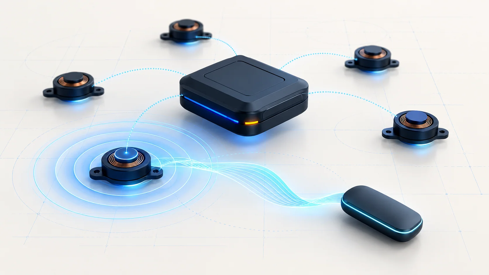
In the sourced keyless access design, the system sends a low-frequency signal through an LF antenna and receives the remote's response through a radio-frequency communication path. The remote, antenna circuits and controller therefore have different roles. The antenna drive circuit is not the entire communication exchange.
Keep three questions separate: can the controller drive the selected antenna circuit, can the intended communication occur, and does the requested vehicle function complete? A successful electrical output check does not by itself prove the remote, return communication, recognition or complete start-authorization system. Likewise, a door that locks mechanically does not prove every keyless antenna circuit is healthy.
The related circuit families
The linked guides provide entry points for distinct reported antenna circuits:
- B1646: driver door LF antenna circuit open.
- B1648: passenger door LF antenna circuit open.
- B1658: rear exterior antenna diagnostic guide.
- B1660: front interior LF antenna circuit open.
- B1664: rear interior LF antenna circuit problem.
- B1668: rear shelf LF antenna circuit open.
Treat these as circuit categories, not six automatic antenna replacement instructions. The sourced rear exterior procedure names a rear bumper antenna; broader trunk or tailgate wording in a catalog is not permission to assume a different Accord body configuration. Rear exterior, rear interior and rear shelf names must not be substituted for one another.
Failure categories and possible symptoms
An open or high-resistance path can be in a wire, terminal connection or the antenna circuit itself. Connector fit and intermittent contact deserve attention before a permanent failed part is assumed. The appropriate diagnostic path may also lead to the controller, but only after the other required checks have separated it from the circuit fault.
Depending on the installed system and affected circuit, a driver may notice inconsistent access near one area, unreliable key detection or a push-button-start concern. Another vehicle may mainly show a stored code during a system check. Do not assume every antenna code causes every access or starting symptom. A broad no-start complaint still needs its own basic diagnosis and may not be caused by the antenna code at all.
Start by confirming the reported fault
Record the customer's affected function and conditions, the available DTCs and relevant scan evidence before clearing information. Confirm basic vehicle power and the correct remote for the vehicle through normal authorized service checks. Establish whether the concern affects one access point or several functions, and inspect accessible connectors or visible damage relevant to the complaint.
Use a suitable scan tool and the applicable system self-check to determine whether the antenna code is current. If it is not reproduced, keep an intermittent connection concern in view rather than declaring that the original complaint was imaginary or permanently repaired. Preserve the original observations and avoid disturbing unrelated wiring while trying to reproduce it.
Separate output, wiring and antenna conclusions
The sourced antenna procedures use a directed functional output check followed, when needed, by isolated wiring checks. The diagnostic value comes from the prescribed setup: the correct circuit is selected, the required connections and power state are established, and the result is interpreted through that specific branch.
Do not replace that setup with a casual voltage reading taken while the system is idle. A missing reading without the required command and conditions is not proof of a failed controller. An observed output is also not a universal proof that the whole access system is working. Follow the exact source before drawing a component conclusion.
For an open-circuit investigation, prove the required paths with the specified components disconnected and the correct power state. Do not measure resistance through powered electronics or apply battery voltage to an unidentified antenna circuit. A single continuity result is not a universal controller replacement verdict. Recheck circuit identity, connector condition and the complete applicable decision path before condemning a module.
Repairs and repair verification
Repair categories include restoring a connection, repairing a proven wire defect, replacing a confirmed faulty antenna or the assembly containing it, and addressing a controller fault only when the full diagnostic path supports that conclusion. On the sourced driver-door configuration, the antenna-related repair can involve the outer handle assembly; do not generalize that packaging or replacement procedure to every antenna.
Follow the applicable requirements for any replacement, setup or authorized registration work. An antenna circuit code is not a reason to alter security settings or replace several modules speculatively.
After repair, repeat the relevant system check and assess whether the code returns. Separately verify the customer's original access or key-detection function under safe conditions, including the affected area where applicable. Code clearance, a successful circuit test and restored customer operation are complementary evidence, not interchangeable definitions of success.
Safety and authorization boundaries
Work only on a vehicle you are authorized to service and keep normal access available so testing cannot leave someone locked out or trapped. Prevent unintended vehicle movement or starting, and provide appropriate ventilation if a running-engine check is required. Follow the applicable electrical isolation and SRS precautions before trim, door or interior work; do not probe SRS circuits.
This overview contains no key cloning, credential extraction, remote replay or immobilizer bypass instructions. Do not bridge unknown terminals, inject power into an antenna circuit or defeat a safety or security function to make a symptom disappear. The goal is to prove a failed electrical path and restore the intended operation, not to circumvent it.