An ignition-power circuit code is a reason to examine the circuit's reported state, its wiring, and the directed relay test. It is not, by itself, proof that the start/stop button, a relay box, or a keyless control unit needs replacement.
This overview sits in the 2010–2017 Honda Accord 2.4 Gas library and concerns vehicles equipped with the applicable one-push start and keyless access power-control system. That family range does not mean every year, body style, or trim has this equipment. The directly reviewed circuit examples apply to an equipped 2017 Accord Sedan 2.4. They do not establish the same hardware, wiring, code availability, or test procedure for the 2010 endpoint or every intervening configuration. Confirm the actual equipment and use the applicable service information for circuit identification, power modes, tool commands, test conditions, and repairs.
What the system does
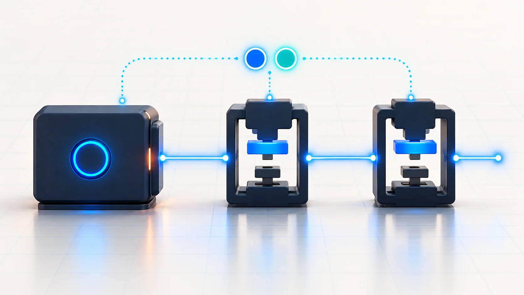
On the equipped system, selecting a power mode involves more than operating a mechanical ignition switch. The start/stop button is part of the power-mode interface, while the power-control system works with ignition relay circuits. Diagnostic information includes the monitored ignition-circuit state, which helps the technician separate a reproducible circuit concern from a code that is not returning during the test.
For diagnosis, keep three observations separate:
- Requested operating mode: what mode the applicable procedure calls for and what the driver requested.
- Reported circuit state: the relevant ignition-circuit data available through the diagnostic tool.
- Circuit behavior under the directed test: whether the wiring and relay circuit meet the applicable checks.
A displayed voltage state is evidence for the next branch of the chart. It does not prove that every downstream load receives usable power, and it does not establish that the complete start-authorization process is working. These circuit guides are not a substitute for a full no-start or key-recognition diagnosis.
Two codes, two ignition-circuit branches
| STEP guide | What it helps organize |
|---|---|
| B12D1 — Keyless Access Power Control Unit IG1B Circuit Error | The IG1B-related power-control circuit concern. Confirm the fault and use the applicable monitored-state and relay-test branches before deciding between a wiring repair and a relay-box repair. |
| B12D2 — Keyless Access Power Control Unit | The IG2-related circuit concern in the reviewed source configuration. Keep its circuit identity separate from the IG1B branch and follow the exact vehicle's chart. |
The circuit names are not interchangeable. Before disconnecting, probing, or replacing anything, reconcile the DTC, the data item, the wiring diagram, and the referred test. If a relay name or decision label does not agree with the circuit under investigation, stop and resolve the discrepancy using the applicable service information. Do not silently substitute another relay's procedure.
Failure categories and possible symptoms
A circuit held at an unintended powered state. A short to power is one diagnostic category in the reviewed charts. The reported state and the directed relay-box test help distinguish a wiring concern from a relay-circuit concern; the code alone does not make that distinction.
A circuit that does not establish the expected state. An open or high-resistance connection is another category. A wire, terminal, connector, or relay circuit remains a candidate until the relevant checks support it. Do not assume that a relay sound or a single scan-data observation proves the whole power path is good.
A relay-box fault established by testing. The reviewed procedures refer to a separate subrelay-box test. Its results matter before a box is condemned. This is not an instruction to exchange relays indiscriminately or to replace the power-control unit because its name appears in a DTC description.
An intermittent concern or added-equipment influence. The source procedures call attention to aftermarket accessories before deeper diagnosis. Record remote-start, alarm, or other added electrical equipment if present, and assess it through the applicable diagnostic process. Do not blame an accessory without evidence. A code that does not return during confirmation is a nonreproduced fault at that time, not proof of a permanent repair.
A customer may report inconsistent power-mode operation, abnormal one-push start behavior, or no obvious symptom beyond a stored code. These are possible observations, not a guaranteed symptom list. Many faults can produce a no-start complaint; retain the broader starting-system context when the evidence calls for it.
A practical diagnostic strategy
- Confirm configuration and history. Establish that the relevant one-push start system is fitted. Record the affected operating mode, customer complaint, recent electrical work, and added accessories.
- Preserve the initial evidence. Read the relevant body and start-system codes with a capable diagnostic tool before clearing them. An engine-only code reader may not provide the required access. Check related faults and the applicable diagnostic order.
- Verify whether the fault returns. Follow the exact chart's mode sequence and waiting conditions, then recheck the DTCs. Timing and mode selection belong to the source-specific procedure; a casual button press is not an equivalent confirmation test.
- Use the correct circuit data to select a branch. Keep IG1B and IG2 observations separate. Record the mode and conditions alongside the data so that a later measurement is not compared with a different operating state.
- Perform the directed wiring and relay tests. Use the correct diagram, connector identification, isolation conditions, and referred test. Distinguish a wiring repair from a relay-box fault using evidence rather than a parts substitution guess.
- Repeat the required confirmation after repair. Verify the intended mode behavior and repeat the applicable DTC check. If the original symptom was intermittent, document what was and was not reproduced.
The useful principle is to connect the operating conditions, reported state, and component test. None of those observations should be stretched into proof of an unrelated function.
Repair categories and verification
Supported repairs may include correcting a diagnosed short, restoring a proven open or high-resistance connection, addressing a demonstrated added-equipment interference, or replacing a relay-box assembly after its specified test establishes the fault. Follow any configuration-specific setup and verification requirements after component service.
Keep the repair record explicit: which fault was reproduced, which test isolated it, what changed, and which mode and DTC checks passed afterward. Restored mode operation and absence of a returning circuit code are separate results. Neither result, alone, proves every starting or security function has been tested.
Safety around ignition-power circuits
Secure the vehicle against movement, select the prescribed test mode, and keep clear of moving engine components. Do not work on a vehicle that may crank or change power state unexpectedly without following the applicable safeguards.
Follow electrical isolation and restraint-system precautions before accessing under-dash wiring or relay equipment. Never probe unfamiliar SRS circuits. Do not measure resistance through powered electronics, jumper an ignition circuit to force operation, or defeat start authorization or interlocks. Any isolated powered test requires the exact manufacturer's connection and protection instructions; the conceptual explanation here supplies no substitute pinout or jumper procedure.