What this code means
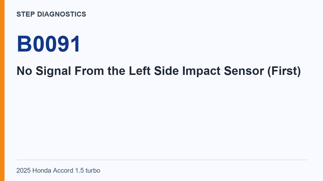
B0091 means the SRS Unit is not receiving a signal from the left side impact sensor (first).
B0091 concerns the signal from the left side impact sensor identified as the first sensor. The diagnostic focus is the connection between that sensor and the SRS unit. A missing signal has to be considered together with the circuit checks and the sensor comparison described below.
The procedure separates several kinds of circuit condition. An open path, a connection between the paths, a connection to ground and an unwanted power condition are checked separately. A result from one of those checks answers that particular circuit question; it does not replace the remaining inspections.
What the vehicle may do
- The SRS Unit has no signal from the left side impact sensor (first).
Possible fault areas
- There may be a problem in the LS1+ or LS1- circuit.
- The left side impact sensor (first) may be faulty.
- Other related components may have a problem.
- The SRS unit may have a problem.
After the confirmation and connector preparation, the diagnosis works through the LS1+ and LS1- checks in the stated order. The test conditions and probe locations change between the inspections. Read each measurement with its own connector state and result criterion.
The known-good sensor comparison comes after the circuit inspection. It introduces a separate result: whether the failure is reproduced with the known-good component. The SRS-unit decision remains conditional on the other inspection items showing normal results.
Diagnostic path
Understand the stored condition
B0091 is No Signal From the Left Side Impact Sensor (First). In plain terms, the SRS Unit is not receiving that left side impact sensor signal, so this diagnostic path can separate an LS1 circuit problem from a sensor, related component, or SRS unit problem.
Before starting
Before beginning this SRS diagnosis, use the SRS precautions and procedures, and handle 12 volt battery terminal disconnection and reconnection by the specified procedure. Also find out whether the vehicle was in a collision. If it was, verify that all required components were replaced with new components of the correct part number and were properly installed.
Initial confirmation
Turn the vehicle to the ON mode, then wait for 10 seconds before moving into the circuit inspection.
Safe connector preparation
Before disconnecting any SRS related connector, do the 12 volt battery terminal disconnection procedure and wait for at least 3 minutes. Then, for the LS1+ and LS1- circuit inspection, disconnect SRS unit connector B, 57P, and disconnect the left side impact sensor (first) connector, 2P.
LS1+ and LS1- shorted wire-to-wire check
With IG Mode OFF, inspect for a shorted wire to wire condition between SRS unit connector B, 57P, female terminals 52 and 53. The expected result is more than 1 MΩ.
LS1+ open wire check
With IG Mode OFF, inspect the LS1+ open wire path between SRS unit connector B, 57P, female terminal 53 and left side impact sensor (first) connector, 2P, female terminal 2. The expected result is less than 1 Ω.
LS1- open wire check
With IG Mode OFF, inspect the LS1- open wire path between SRS unit connector B, 57P, female terminal 52 and left side impact sensor (first) connector, 2P, female terminal 1. The expected result is less than 1 Ω.
LS1+ shorted-to-ground check
With IG Mode OFF, inspect LS1+ for a short to ground at SRS unit connector B, 57P, female terminal 53. The expected result is more than 1 MΩ.
LS1- shorted-to-ground check
With IG Mode OFF, inspect LS1- for a short to ground at SRS unit connector B, 57P, female terminal 52. The expected result is more than 1 MΩ.
LS1+ shorted-to-power check
With IG Mode ON, inspect LS1+ for a short to power at SRS unit connector B, 57P, female terminal 53. The expected result is not shorted.
LS1- shorted-to-power check
With IG Mode ON, inspect LS1- for a short to power at SRS unit connector B, 57P, female terminal 52. The expected result is not shorted.
Evaluate the circuit inspection
Now evaluate the LS1+ and LS1- circuit inspection results. If the circuit inspection is abnormal, there is a problem in the circuit.
Known-good sensor inspection
This inspection evaluates the component using a known-good component. Install a known-good left side impact sensor (first), then attempt to reproduce the failure.
The known-good comparison is an indirect way to evaluate the sensor within this diagnostic path. Use the result of reproducing the failure to follow the stated branch. This is different from the earlier wire measurements: the question here is whether changing to the known-good component changes the observed failure condition.
Evaluate the sensor inspection
Evaluate the left side impact sensor (first) inspection results. If the failure is reproduced, there is a problem with other related components. If the symptom or DTC goes away, the left side impact sensor (first) must be faulty.
SRS unit decision point
For SRS unit inspection, if the other inspection items indicated a normal condition, then it is determined that the remaining SRS unit is the cause. That result means there is a problem with the SRS unit.
Takeaway
The clean path on this code is collision history first, then safe SRS connector handling, then LS1 circuit checks, the known-good left side impact sensor check, and finally the SRS unit decision point if the other inspections are normal.
Final check
The documented path can separate circuit faults from sensor, related component, or SRS unit faults.
Keep the circuit-inspection conclusion, the known-good sensor result and the SRS-unit decision as separate findings. That preserves the logic of the diagnosis: first establish the state of the paths, then interpret the component comparison, and apply the remaining-unit conclusion only under its stated conditions.