What this code means
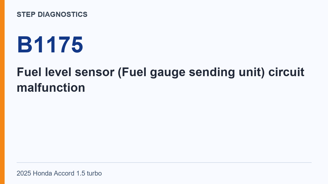
B1175 can indicate a persistent open-circuit signal from the fuel gauge sending unit.
B1175 concerns the fuel level sensor, also called the fuel gauge sending unit. The stored condition is a persistent open-circuit signal. The procedure considers the sending unit, the connecting paths and the module reached at the end of the inspection logic.
An open-circuit indication identifies the electrical condition being reported. The diagnosis then has to place that condition in the appropriate part of the path. That is why the sending-unit work and the individual wire measurements remain separate stages.
What the vehicle may do
- The sending-unit signal may remain in an open-circuit state.
- The gauge control module can store B1175 when that state persists.
Possible fault areas
- The fuel gauge sending unit may be involved.
- The sending-unit circuit may have an open wire.
- The gauge control module may be involved.
Start with the confirmation and sending-unit check, then follow the connector preparation for the wiring inspections. The two terminal pairs identify different paths. The normal reading must be compared with the pair that was actually measured.
The result logic is applied after those measurements. An abnormal wiring result belongs to the circuit inspection. The module conclusion is reached only when the preceding inspection items are normal, as stated in the final branch.
Diagnostic path
Understand the stored condition
B1175 identifies a Fuel level sensor (Fuel gauge sending unit) circuit malfunction. We will call it the sending unit from here. The gauge control module monitors the sending unit’s signal. It stores B1175 if that signal stays in an open-circuit state continuously for a set time.
Before troubleshooting
If you are troubleshooting multiple DTCs, follow “B-CAN System Diagnosis Test Mode A.” This is required when troubleshooting multiple DTCs.
Initial confirmation
To confirm the code, turn the vehicle to the ON mode. Wait for at least 30 seconds.
Sending-unit check
Next, perform the Fuel Gauge Sending Unit Test. Any later conclusion about the gauge control module depends on this required test showing a normal condition.
Prepare for the wiring checks
Disconnect the fuel tank unit connector (4P) for the FUEL_GAUGE+, FUEL_GAUGE- Open Wire Inspection. Disconnect gauge control module connector A (32P). Keep both connectors disconnected for the following measurements. Use IG Mode OFF for both checks.
Check terminals 2 and 8
Keep both connectors disconnected and IG Mode OFF. To check resistance, place one probe on fuel tank unit connector (4P) female terminal 2.
- Other probe: gauge control module connector A (32P) female terminal 8.
- Normal reading: less than 1 ohm.
That reading means this terminal pair passes the open-wire inspection.
The wire pairs connect different terminals of the fuel tank unit to the gauge control module. Fuel tank unit connector terminal 2 pairs with module connector A terminal 8; tank-unit terminal 4 pairs with module terminal 9. Both paths use the less-than-1-ohm criterion under the stated disconnected-connector conditions.
These measurements examine the connecting paths. They are separate from the sending-unit check that appears earlier in the procedure. The final gauge-control-module conclusion depends on the required sending-unit result and the other inspection results being normal. A normal wire reading alone is therefore only part of that final condition.
Check terminals 4 and 9
Keep both connectors disconnected and IG Mode OFF. To check resistance, place one probe on fuel tank unit connector (4P) female terminal 4.
- Other probe: gauge control module connector A (32P) female terminal 9.
- Normal reading: less than 1 ohm.
That reading means this terminal pair passes the open-wire inspection.
What the wiring results mean
Use the external circuit inspection result. If the open-wire inspection is abnormal, there is a problem in the circuit.
When the module becomes the cause
The Gauge Control Module Inspection requires all the other inspection items to show a normal condition first. That includes the required Fuel Gauge Sending Unit Test, not just the wiring checks. Only if those checks are normal is the gauge control module determined to be the cause. Without the sending-unit test method and its normal result, that conclusion remains conditional.
Takeaway
B1175 can involve the sending unit, its circuit, or the gauge control module. Normal wiring results alone do not establish the module as the cause.
Final check
B1175 can involve the sending unit, its circuit, or the gauge control module; the module conclusion depends on the other inspections showing normal conditions.
Use the sending-unit finding and the two wiring results together. Do not collapse them into a single general observation about the fuel gauge. The final branch depends on which inspection is normal or abnormal, and the module conclusion depends on the earlier checks being normal.