Applicability and service-information boundary
This overview applies to the STEP vehicle group for the 2016-2024 Honda Civic 1.5 Turbo Gas. Exact vehicle listings confirm the Civic Sedan with the L15B7 engine in 2016, 2020, and 2024. The detailed network descriptions and diagnostic paths used for this article were verified on a 2024 Honda Civic Sedan L15B7.
The high-level diagnostic principles apply across the named vehicle group, but the network layout is not safely interchangeable by year, body style, trim, or equipment. A module may move to a different network segment, communicate through a different gateway path, or be absent on another configuration. Exact topology, DTC definition, scan-tool function, connector identity, wiring, test value, safety sequence, programming step, and repair procedure must come from service information for the vehicle being repaired.
What the vehicle network system does
A modern Civic does not operate as one computer with a large wiring harness. It uses many control units that exchange messages over shared communication networks. A module can use information created somewhere else in the vehicle without requiring a dedicated wire for every signal.
The network has to accomplish several jobs:
- Move time-sensitive powertrain, braking, steering, restraint, driver-support, body, and display information between control units.
- Let modules identify and use only the messages relevant to their functions.
- Connect separate network segments through a gateway where required.
- Let a scan tool communicate with modules and report communication status.
- Put selected body modules into lower-power states and wake them when required.
- Detect missing, invalid, or bus-disrupting communication and store evidence for diagnosis.
A communication DTC describes a failed information exchange. It does not automatically identify a failed module.
CAN, LIN, and the gateway at a useful level
The verified late configuration uses Controller Area Network, or CAN, for communication among multiple control units. CAN is a shared, multi-master network: several modules can transmit, receive, and prioritize messages on the same communication path. The system also uses Local Interconnect Network, or LIN, for selected local functions that do not need the same communication capability.
Honda separates communication into multiple functional network segments. At a high level:
- F-CAN carries powertrain and chassis information. Engine, transmission, braking, steering, restraint, and other dynamic systems depend on timely data exchange.
- B-CAN carries body-related information. Lighting, locks, displays, parking-aid information, and other body functions may communicate through this side of the network.
- LIN connects selected local devices to a master control unit. A LIN concern may affect one local function without taking down a main CAN segment.
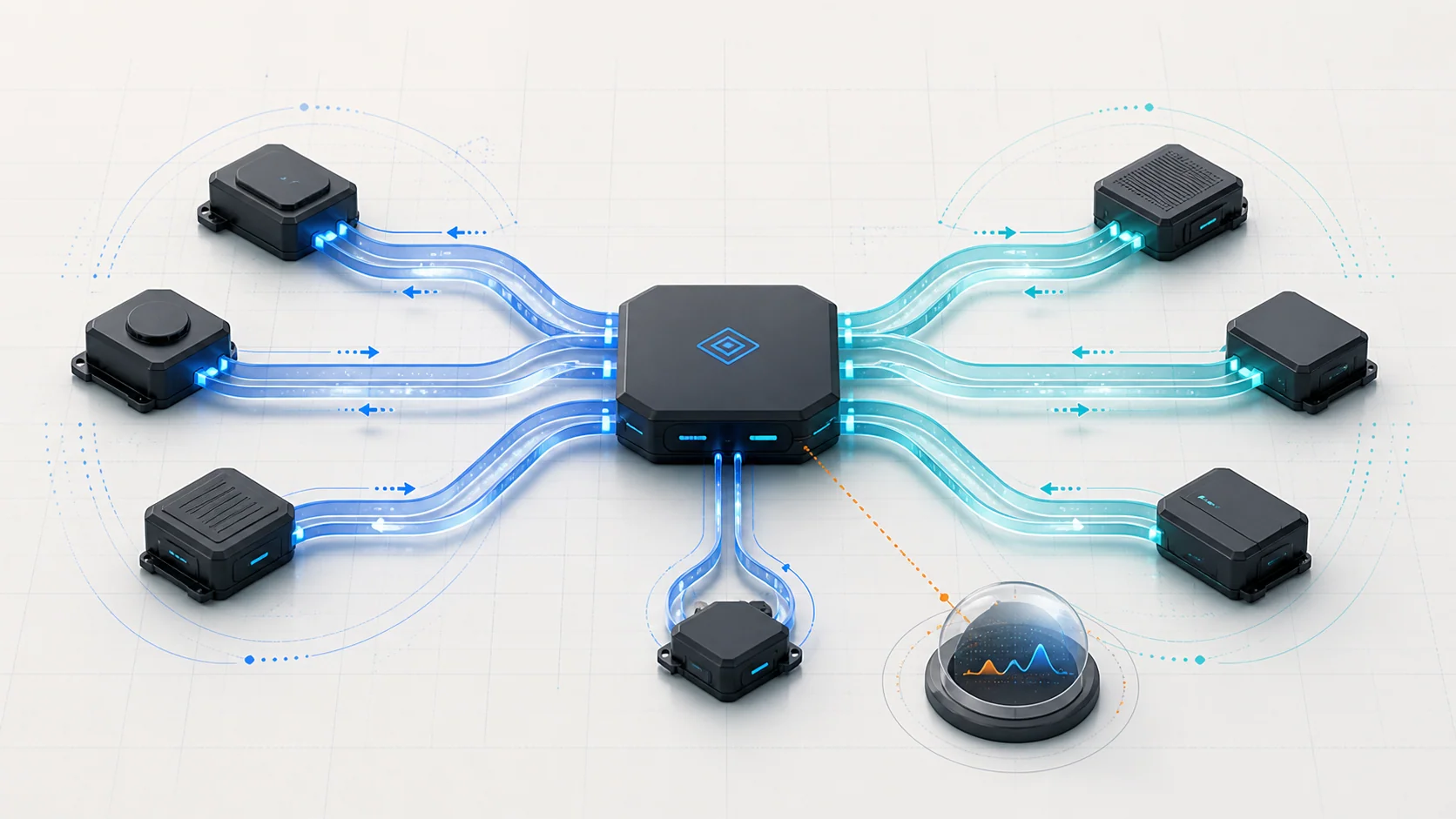
- The CAN gateway connects network segments. It provides a path for messages and diagnostic communication between parts of the vehicle that are not on one shared pair of network wires.
The exact late-model network is more segmented than those four bullets suggest. That is why the applicable topology matters. A mechanic needs to know which modules share a branch, which route passes through the gateway, and which module is reporting the fault before opening a connector or testing a circuit.
How a communication DTC is created
Most U-codes in this article involve one control unit expecting information from another. The code can be understood by answering three questions:
- Who stored the code? This is the reporting module.
- Whose message or data is missing? This is the expected sender or source.
- What communication and power path connects them? This includes the sender's power and ground, the relevant network branch, connectors, gateway path, and the reporting module's own ability to communicate.
If a gauge module stores a code for missing parking-sensor data, the code proves that the gauge module did not receive the expected data under the monitored condition. It does not prove that the gauge module, the parking-sensor module, or the gateway is defective. A sender that never powered up can look identical to an open network branch from the reporter's point of view.
The same logic applies to powertrain, ABS/VSA, EPS, and SRS communication codes. Always separate the observer, the missing sender, and the path.
Bus-off is different from one missing message
A lost-communication code can be limited to one module or one path. A bus-off code indicates that communication on a network segment has been disrupted severely enough for a controller or gateway to stop normal participation on that bus.
On the verified late configuration, U0029 concerns a PF-CAN A bus-off condition observed through the CAN gateway path. Its diagnostic categories include the external bus circuit, units connected to that bus, and the gateway. That is broader than a simple verdict on the PCM or gateway.
One shorted branch or connected unit can disturb other modules that share the segment. The resulting scan may contain many secondary communication codes. Diagnose the bus-wide condition and related gateway evidence before treating each downstream U-code as a separate failure.
What the related DTCs are telling you
| DTC | Communication category | What it directs you to prove |
|---|---|---|
| U0029 | PF-CAN A bus-off behavior | Whether the problem is bus-wide, whether the external circuit or a connected unit is disrupting communication, and whether gateway-side evidence changes diagnostic priority |
| U0100 | Missing PCM/ECM communication | Whether the powertrain controller powers up normally and whether its expected messages can pass through the applicable network and gateway path |
| U0122 | Missing VSA/ABS-side communication | Whether the VSA control unit is powered and awake and whether the relevant chassis-network path carries its data |
| U0131 | Missing EPS communication | Whether the EPS control unit starts normally and whether the expected steering data can travel through the applicable CAN path |
| U0151 | Missing SRS communication | Whether the SRS unit is powered and communicating and whether the network path is intact, while following the applicable restraint-system safety procedure |
| U1288 | Gauge module missing parking-aid data | Whether the parking and back-up sensor control unit starts normally, whether multiple network codes indicate a wider condition, and whether the expected data reaches the reporting module |
These descriptions are diagnostic categories, not universal code definitions for every Civic configuration. Confirm the complete DTC, subcode, storing module, and service information for the vehicle in front of you.
What the driver or technician may notice
Possible observations include:
- multiple warning indicators appearing together;
- no-start, abnormal starting, or a module that does not wake up;
- unavailable ABS/VSA, steering-assist, restraint, parking-aid, display, or driver-support information;
- a scan tool that cannot communicate with one module or several modules;
- a system that works after cycling the ignition but later fails again;
- many U-codes stored at the same time after a low-voltage event or electrical repair;
- intermittent symptoms when a harness, connector, or recently disturbed area moves;
- normal mechanical operation in one system even though another module reports its data as missing.
The symptom does not establish the failed section. A warning lamp may be a receiving module's response to missing data rather than evidence of a mechanical fault in that system.
Preserve evidence before disconnecting power
Do not begin network diagnosis by disconnecting the battery or clearing every DTC. That can erase the pattern showing which modules were online, which module reported first, and whether the fault was current or intermittent.
Before changing the vehicle's electrical state, record:
- every confirmed, pending, and history DTC with its storing module and subcode;
- which modules communicate and which do not;
- communication-status or network-test results available on the scan tool;
- system voltage and the circumstances of any recent discharge, jump-start, battery replacement, collision, water intrusion, programming, or module work;
- freeze-frame, snapshot, or failure-record information when available;
- warning indicators and functions that are currently unavailable.
After evidence is preserved, follow the applicable battery-disconnection and reconnection procedure when connector or wiring work requires it. Some systems can need resets, learning, initialization, or post-reconnection checks.
SRS and electrical safety
U0151 involves restraint-system communication. Do not probe, disconnect, substitute, or disturb an SRS unit or SRS-related connector using a general network routine. Follow the exact SRS precautions, battery-disconnection procedure, waiting period, connector-handling rules, and approved test method for the vehicle.
Also avoid bridging network terminals, applying power to communication circuits, or using a test light on an unknown module circuit. Use the specified high-impedance meter, breakout method, scan-tool function, and wiring information. If a procedure requires modules to be disconnected, preserve the correct power state and protect terminals from damage or spread.
Common failure categories
1. The expected sender is not powered or awake
A module with a missing power feed, weak ground, disabled relay path, damaged connector, or internal startup problem cannot send messages. Other modules then store communication DTCs even when the network wiring itself is intact.
This is why the verified U0100, U0122, U0131, U0151, and U1288 paths place power and ground ahead of a module verdict. Prove that the expected sender can start normally before judging its network output.
2. One network branch is open
An open high or low communication circuit, disconnected connector, backed-out terminal, or damaged splice can isolate one module or a branch. Modules elsewhere on the network may continue to communicate normally.
The scan pattern and topology help locate the boundary. If every module beyond one connection is offline, the shared path is more useful evidence than the first module named by a code.
3. A branch or connected unit disrupts the bus
A short between network circuits, a short to power or ground, terminal damage, water intrusion, or a connected control unit can distort the shared bus. Several modules may disappear together, and a bus-off DTC may become the primary clue.
Isolation must follow the applicable procedure. Randomly unplugging modules can create more codes, erase the original state, or involve SRS and other safety-sensitive circuits.
4. Gateway communication is interrupted
When the path between a reporting module and an expected sender crosses the CAN gateway, the gateway, its power and grounds, its network branches, and the sender's branch all matter. A gateway-related code can take priority because one gateway-side fault can explain multiple missing-module codes.
Do not replace the gateway because it appears in the route. Prove the surrounding circuits and connected-unit behavior first.
5. The fault is intermittent
Loose terminals, harness tension, corrosion, moisture, poor repairs, vibration, temperature, and unstable voltage can interrupt communication briefly. The vehicle may communicate normally by the time it reaches the bay.
History codes, failure records, recent repair areas, and a controlled wiggle or load test performed under the applicable procedure can be more useful than a static resistance reading after the fault disappears.
6. Sleep, wakeup, or vehicle-state behavior is misunderstood
Selected body modules enter low-power states and wake in response to network or local inputs. Testing a module in the wrong vehicle mode can make normal sleep behavior look like a communication failure or can prevent a monitor from running.
Use the specified vehicle mode and timing for the exact diagnostic path, but keep those details in the service procedure rather than applying one year's sequence across the range.
A practical network diagnostic strategy
Step 1: Identify the exact vehicle and code reporter
Confirm model year, body style, engine, equipment, complete DTC, subcode, and storing module. Open the applicable network topology and code definition. A generic U0100 label is not enough to choose connector tests.
Step 2: Preserve a complete network scan
Record the full module scan before clearing codes or disconnecting power. Separate modules that communicate normally, modules that are absent, and modules that store secondary lost-data codes.
Step 3: Check voltage history and basic electrical condition
Confirm battery and charging-system condition, terminal integrity, and relevant power-distribution concerns. A low-voltage or interrupted-power event can create a large U-code set without a permanent network wiring failure.
Step 4: Find the primary pattern
Ask whether the concern affects:
- one reporting relationship;
- one module and all of its data;
- several modules on one branch;
- modules across a gateway path;
- most of a network segment;
- or the scan tool's access to the vehicle.
A bus-off or gateway-side code can explain many secondary lost-communication codes. Work the highest-level shared condition first.
Step 5: Prove the expected sender's power and ground
Before testing the bus or replacing a module, prove that the expected sender has the feeds, grounds, and wakeup conditions specified for the vehicle. Use loaded circuit evidence where the procedure requires it; an unloaded voltage reading may not prove the circuit can support the module.
Step 6: Use topology and communication-status data
Compare the offline modules with the exact network map. Use the scan tool's applicable communication-status or network-test function to determine which branch or module is not responding. Do not copy a channel name or module list from a different year.
Step 7: Inspect the physical path
Inspect accessible connectors, harness routing, splices, grounds, recent repair areas, collision zones, water-entry points, and areas exposed to heat or movement. Look for terminal spread, poor retention, corrosion, pin damage, and nonstandard repairs without disturbing safety-sensitive connectors unnecessarily.
Step 8: Test and isolate only through the exact procedure
Perform the specified network-circuit checks with the required vehicle mode, modules connected or disconnected as directed, and the correct terminal references. If the procedure isolates connected units one at a time, follow its order and safety controls. Do not use a remembered CAN resistance value or connector pinout from another Civic as a universal test.
Step 9: Verify communication, not only code clearing
After repair, restore every connection and complete required battery, module, steering, restraint, or other initialization steps. Repeat a full network scan and the applicable communication-status check. Confirm the repaired module and the reporting module both communicate, related warning indicators behave normally, and no primary or pending U-code returns under the original condition.
Clearing codes while the monitor has not rerun is not repair verification.
Match the repair to the proven failure
The repair may involve a battery or charging concern, a fuse or relay path, a power or ground circuit, connector-terminal repair, harness or splice repair, water-intrusion correction, a gateway branch, or a control unit that has been isolated by the proper procedure. Some module repairs also require programming, setup, calibration, or system-specific verification.
Replace a module only after its power, ground, communication path, connected-unit influence, and applicable substitution or decision criteria support that conclusion. A network code is not permission to install a PCM, VSA unit, EPS unit, SRS unit, gauge module, parking-sensor module, or gateway.
Final takeaway
Vehicle-network diagnosis on the 2016-2024 Honda Civic 1.5 Turbo Gas becomes manageable when the code is treated as an information-flow problem. Identify who stored the code, whose message is missing, and what powered network path connects them. Then use the complete scan pattern to decide whether the concern is local, branch-wide, gateway-related, or bus-wide.
Preserve evidence, verify voltage and module power/ground, use the exact topology, isolate the circuit safely, and confirm communication after repair. The linked STEP guides introduce the six diagnostic categories; the applicable service information for the Civic being repaired controls every exact test and repair decision.