What this code means
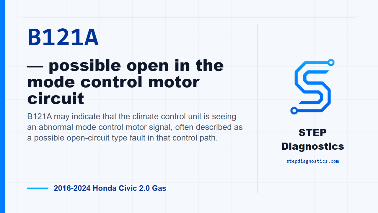
B121A may indicate that the climate control unit is seeing an abnormal mode control motor signal, often described as a possible open-circuit type fault in that control path.
What the vehicle may do
- Airflow mode may not change correctly between vents, floor, or defrost positions.
- The HVAC system may respond inconsistently to mode changes.
- The climate control system may store the fault even if the symptom is intermittent.
Possible fault areas
- Possible open or high-resistance wiring in the mode control motor signal path.
- Possible issue at the mode control motor connector or related circuit connections.
- Possible mode control motor fault area.
- Possible climate control unit fault area.
Diagnostic path
Open
Today we’re looking at B121A on a 2016 to 2024 Honda Civic with the 2.0 gas engine. In plain terms, the climate control unit may be seeing an open or abnormal signal in the mode control motor circuit. The driver may notice the air outlets do not change modes correctly, or the HVAC case may not respond the way it should. Broadly, this can involve the mode control motor circuit wiring, the mode control motor side of the circuit, related components in that signal path, or the climate control unit itself. The code sets when the input voltage from the mode control motor is higher than the specified value, so treat this as a signal and circuit plausibility diagnosis, not as a parts call.
Confirm the fault condition
Before you get into the code-specific checks, start with the basic troubleshooting approach so the vehicle, power supply, connectors, and overall system condition are not being overlooked. Then put the vehicle in ON mode. That is the confirmation condition for this diagnostic path. If other codes or basic system issues are present, handle those in a structured way first so you are not chasing a symptom caused somewhere else.
Check the open-wire side first
The first actual circuit check is the MDD-P and SENS-COM open-wire inspection. With IG Mode OFF for this part of the test, disconnect the mode control motor 5P connector, and disconnect climate control unit connector B, the 24P connector. Then perform the open-wire checks in order. On the MDD-P circuit, normal is less than 1 Ω. On the SENS-COM circuit, normal is also less than 1 Ω. If either result is abnormal, the diagnostic direction is a circuit problem, so stay with the wiring side before moving on.
Move to the mode control motor side
There is no direct standalone component test for the mode control motor itself, so the diagnosis works through the related circuits and components. For the mode control motor inspection, disconnect the mode control motor 5P connector. With IG Mode ON, check the unit output voltage at the disconnected mode control motor 5P connector female terminals. Normal is about 5 V. If that output voltage is normal, the path points toward a problem with the mode control motor. If it is abnormal, the path points toward other related components instead.
Check the climate control unit side
Next is the climate control unit inspection. Disconnect the mode control motor 5P connector, then with IG Mode ON, check the unit internal circuit at the connected climate control unit connector B, the 24P connector, on the female terminals. Normal is about 5 V. If this check is abnormal, the diagnostic direction is a problem with the climate control unit. If your readings do not line up cleanly with the path, pause, recheck the earlier diagnostic steps, confirm the connector setup and test points, and avoid guessing.
Verify separately and close
Keep verification separate from the testing. After the fault found in the diagnostic path is corrected, return the vehicle to ON mode and confirm B121A does not reset under the same confirmation condition. The takeaway is simple: prove the low-resistance wiring path first, then prove the 5 V signal side, and let the test results point you to the circuit, the mode control motor side, related components, or the climate control unit side. For more diagnostic training, visit stepdiagnostics.com.
Final check
This diagnosis is best handled by following the circuit checks in order and using the measured results to narrow the fault area.
For more guided automotive diagnostics, visit STEP Diagnostics.