What this code means
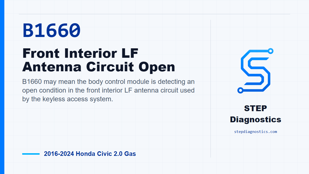
B1660 may mean the body control module is detecting an open condition in the front interior LF antenna circuit used by the keyless access system.
What the vehicle may do
- The vehicle may have inconsistent keyless access operation.
- Interior key detection can be limited or unreliable.
- The warning behavior can vary depending on the rest of the keyless access system status.
Possible fault areas
- A possible open in the front interior LF antenna wiring path.
- Possible connector or antenna concerns in the front interior LF antenna circuit.
- A possible body control module circuit concern.
Diagnostic path
Open and code context
On this Civic, B1660 is for the front interior LF antenna circuit being seen as open by the keyless access control side of the body control module. In plain terms, the module may not be seeing a complete antenna circuit, so the vehicle can have keyless access behavior that is inconsistent or limited around interior key detection. The broad areas to keep in mind are a possible open in the antenna wiring, a connector or antenna issue, or a body control module circuit problem. Start with the basic system checks first, and if other body network codes are present, handle that network diagnostic path before chasing this one too far.
Initial scan check
Next, run the HDS Self Check. Do not skip this part. It gives you the current body system status before you start unplugging connectors and testing the antenna circuit. Once you have that baseline, move into the open-circuit checks for the front interior LF antenna lines.
Prepare for the antenna line open checks
For the EXT_F+ and EXT_F- open wire inspection, turn the vehicle to IG Mode OFF. Then disconnect the front interior LF antenna 2P connector and disconnect body control module connector C, the 66P connector. Before probing, make sure the exact connector terminals are positively identified from the connector views and the vehicle in front of you. Do not guess at terminal locations.
Check the EXT_F+ and EXT_F- circuits
With the connectors disconnected and IG Mode OFF, perform the EXT_F+ open wire inspection first. A normal result is less than 1 Ω. Then perform the EXT_F- open wire inspection the same way. That circuit is also normal at less than 1 Ω. If either open wire inspection is abnormal, stay on the circuit side of the diagnosis because the fault is in the wiring path you just tested.
Check the body control module side
If the external circuit checks normal, move to the body control module inspection. The setup for this part is to disconnect the front interior LF antenna slash initiator 2P connector. Then perform the module internal circuit inspection with IG Mode ON and look for the expected voltage result. If this inspection is abnormal, the diagnostic path points to a problem with the body control module.
Narrow the remaining fault area
If the circuit checks are normal and the body control module inspection is normal, then the remaining fault area in this diagnostic path is the front interior LF antenna. At that point, do not keep retesting random parts of the system. Pause, recheck the earlier diagnostic path, confirm the connector condition and test setup, and avoid guessing.
Verification and takeaway
After the fault area is corrected, verify the repair and confirm B1660 stays gone. The clean takeaway is simple: prove the two antenna lines first, then prove the module side, and only then narrow the remaining fault area to the front interior LF antenna. For more diagnostic training, visit stepdiagnostics.com.
Final check
B1660 is best approached by confirming the antenna circuit path first, then checking the module side, and only then narrowing the remaining fault area.
For more guided automotive diagnostics, visit STEP Diagnostics.