What this code means
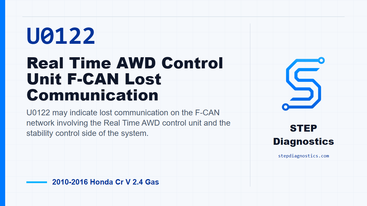
U0122 may indicate lost communication on the F-CAN network involving the Real Time AWD control unit and the stability control side of the system.
What the vehicle may do
- The vehicle may show AWD or stability-related warning indicators.
- AWD or stability functions can be limited while the communication fault is active.
- The code can be intermittent if the fault is not present during the current check.
Possible fault areas
- Possible F-CAN_H or F-CAN_L wiring or connector issues between modules.
- Possible VSA modulator-control unit software concern.
- Possible control unit communication issue.
Diagnostic path
Opening context
This episode is for U0122 on a 2010 to 2016 Honda CR-V with the 2.4 gas engine. In plain terms, this code may mean the Real Time AWD control unit is losing communication on the F-CAN network with the stability control side of the system. The vehicle may show AWD or stability-related warnings, and AWD or stability functions can be limited while the communication fault is active. Broadly, the possible fault areas can include F-CAN wiring or connector problems between the modules, or a possible control unit software or module issue. Before chasing this code, if any PGM-FI codes are present, handle those first. Then start with the basic system checks and follow a structured diagnostic approach.
Verify the problem first
Start by turning the vehicle to the ON mode. Clear the DTC with the HDS, then turn the vehicle to OFF, or LOCK mode. After that, start the engine and check for DTCs again with the HDS. If U0122 comes right back, the failure is duplicated and you move into the communication checks. If the code does not return, treat it as an intermittent at this time. If captured data is available for this code, try to reproduce the same conditions instead of guessing.
Check the F-CAN lines toward the PCM side first
The shared communication check starts with the F-CAN high and low lines between the Real Time AWD control unit and the PCM. Turn the vehicle to OFF, or LOCK mode, and wait 2 minutes. Then jump the SCS line with the HDS, and wait more than 1 minute. After that, disconnect the Real Time AWD control unit 24P connector and PCM connector A, 51P. Check continuity from Real Time AWD control unit 24P connector terminal No. 14 to PCM connector A, 51P, terminal No. 2, and from Real Time AWD control unit 24P connector terminal No. 24 to PCM connector A, 51P, terminal No. 1. The test condition is vehicle OFF, with the Real Time AWD control unit 24P connector and PCM connector A, 51P, disconnected. At this point, the decision is whether there is continuity on those F-CAN lines.
Check the F-CAN lines for U0122 to the VSA unit
For U0122, the next check is the F-CAN high and low wiring between the Real Time AWD control unit and the VSA modulator-control unit. Turn the vehicle to OFF, or LOCK mode. Disconnect the Real Time AWD control unit 24P connector and the VSA modulator-control unit 38P connector. Then check continuity on each communication line individually: Real Time AWD control unit 24P connector terminal No. 14 to VSA modulator-control unit 38P connector terminal No. 38, and Real Time AWD control unit 24P connector terminal No. 24 to VSA modulator-control unit 38P connector terminal No. 26. The test condition is vehicle OFF, with both of those connectors disconnected. At this point, the decision is simply whether each line has continuity.
Use the U0122 continuity result
If there is no continuity on the VSA leg, repair the open in the F-CAN_H and/or F-CAN_L wires between the Real Time AWD control unit and the VSA modulator-control unit. If there is continuity, the wiring check has passed for this leg of the network. In that case, update the VSA modulator-control unit if it does not have the latest software, then recheck. If the symptom or indication goes away after the update, troubleshooting is complete. If it does not go away after the VSA modulator-control unit is updated, replace the VSA modulator-control unit.
Check the remaining F-CAN leg if the path leads there
The same shared communication path also includes an open-wire check between the Real Time AWD control unit and the steering angle sensor. Turn the vehicle to OFF, or LOCK mode. Disconnect the Real Time AWD control unit 24P connector and the steering angle sensor 4P connector. Then check continuity from Real Time AWD control unit 24P connector terminal No. 14 to steering angle sensor 4P connector terminal No. 2, and from Real Time AWD control unit 24P connector terminal No. 24 to steering angle sensor 4P connector terminal No. 3. The test condition is vehicle OFF, with the Real Time AWD control unit 24P connector disconnected and the steering angle sensor 4P connector disconnected. If the diagnostic path no longer makes sense at this point, pause, recheck the earlier communication path, and avoid guessing.
Verify the repair
After any wiring repair, software update, or module decision, verify the repair by rechecking whether the original symptom or indication is gone and confirm U0122 stays gone. The takeaway is simple: prove the F-CAN wiring path before making the software or module call. For more diagnostic training, visit stepdiagnostics.com.
Final check
For U0122, confirm the code returns, then prove the F-CAN wiring path to the VSA modulator-control unit before making the software or module decision.
For more guided automotive diagnostics, visit STEP Diagnostics.