What this code means
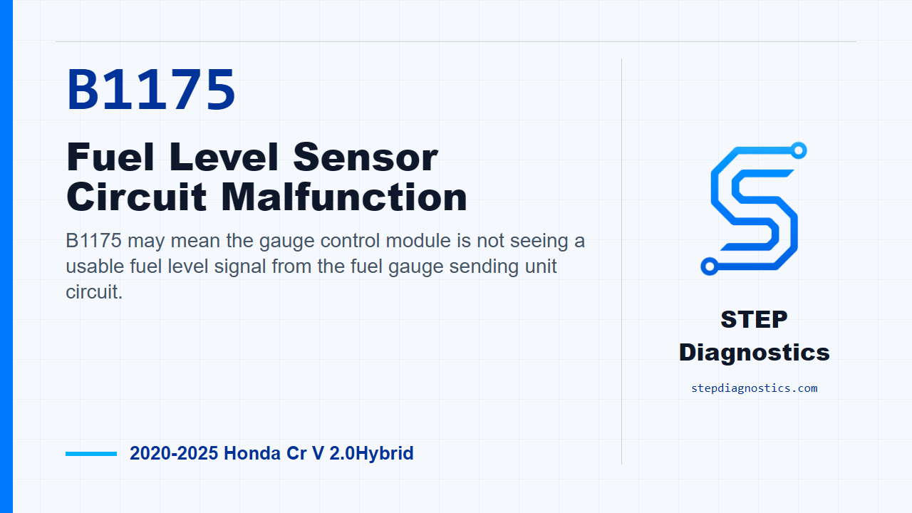
B1175 may mean the gauge control module is not seeing a usable fuel level signal from the fuel gauge sending unit circuit.
What the vehicle may do
- The fuel gauge may read incorrectly.
- The fuel level display may stay fixed or move erratically.
- A warning indicator or stored body-system fault may be present.
Possible fault areas
- Possible fuel gauge sending unit issue.
- Possible open or high-resistance condition in the fuel gauge signal wiring or connectors.
- Possible gauge control module issue after the sender and circuit checks pass.
Diagnostic path
Open on B1175
On this CR-V Hybrid, B1175 points to a fuel level sensor circuit malfunction. In plain terms, the gauge control module may be seeing the fuel gauge sending unit signal as open long enough to flag a fault. The customer may notice an inaccurate or stuck fuel level display, or the gauge may act erratically. The likely fault areas are the sending unit test path, the FUEL_GAUGE positive and negative circuits, their connectors, and, only after the other checks pass, the gauge control module itself.
Start clean before chasing the circuit
Start with the basic system checks. If other codes are present, especially codes that could affect body communication or module data, sort that out first. Do not treat B1175 as an isolated fuel sender problem until the rest of the code picture makes sense.
Confirm the fault
For the confirmation check, turn the vehicle to the ON mode and wait for at least 30 seconds. That gives the gauge control module time to evaluate the fuel gauge sending unit signal before you move into pinpoint testing.
Run the sending unit test
Next, do the fuel gauge sending unit test. This is the first split in the diagnosis: verify the sender side before condemning the wiring path or the gauge control module. The procedure here does not provide additional values for that test, so stay within the test information available to you and do not guess at a pass or fail standard.
Prepare for the open-wire checks
If the path moves to the open-wire inspection, disconnect the fuel tank unit connector, the 4P connector, then disconnect gauge control module connector A, the 32P connector. Before probing, make sure you are on the correct FUEL_GAUGE positive and negative terminals. If the terminal identification is not clear, pause, confirm the connector locations and terminal positions, and avoid guessing.
Check both fuel gauge circuits
With IG Mode OFF, inspect the FUEL_GAUGE positive circuit for an open. Normal is less than 1 Ω. Then inspect the FUEL_GAUGE negative circuit the same way. Normal is also less than 1 Ω. If either side is abnormal, the problem is in the circuit, so stay on the wiring and connector side of the diagnosis.
Only then judge the gauge control module
If the other inspection items all show normal, the remaining suspect in this diagnostic path is the gauge control module. That conclusion comes after the sending unit test and both FUEL_GAUGE circuit checks have been handled in order.
Verify and close
After the fault found in this path is corrected, verify the repair and confirm B1175 stays gone under the same operating conditions. The takeaway is simple: confirm the code, test the sending unit path, prove both fuel gauge wires are below the specified resistance, and only then make a call on the module. For more diagnostic training, visit stepdiagnostics.com.
Final check
B1175 is often approached by confirming the fault, checking the sending unit path, proving the two fuel gauge circuits, and only then judging the module.
For more guided automotive diagnostics, visit STEP Diagnostics.