What this code means
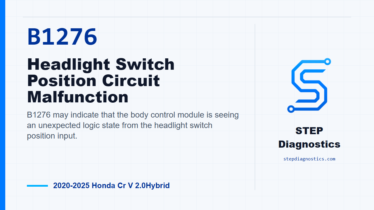
B1276 may indicate that the body control module is seeing an unexpected logic state from the headlight switch position input.
What the vehicle may do
- The vehicle may store a body electrical lighting code.
- Headlight or parking light switch behavior may not match the selected switch position.
- The concern can be intermittent if a connector or wiring issue is present.
Possible fault areas
- Combination light switch input circuits
- Connector condition or wiring continuity concerns
- Possible short-to-ground concerns on the switch signal circuits
- Possible body control module involvement after circuit checks are normal
Diagnostic path
Opening context
Today we’re focused on B1276 on a 2020 to 2025 Honda CR-V 2.0 Hybrid. In plain terms, this code may set when the body control module sees a logic problem in the headlight switch input. The driver may notice lighting switch behavior that does not match the selected position, or there may simply be a stored body electrical code. Broadly, the possible fault areas can include the combination light switch input circuits, connector or wiring issues, and, after the circuit checks pass, a possible body control module fault.
Start with the setup checks
Before getting into circuit testing, start with the basic troubleshooting approach for this system. If other codes are present, do not treat B1276 in isolation. Follow the network diagnosis path for multiple codes first, and if the front lighting control side has a related fault, handle that before chasing the headlight switch position circuit. That keeps you from condemning the switch circuit when another lighting module concern is steering the symptom.
Reproduce the operating conditions
Next, reproduce the operating conditions. Turn the vehicle to ON mode. Then move the headlight switch through each position and hold each position for at least 6 seconds. After that, use the scan tool in Body Electrical, then Lighting, then Data List. The point here is to make the body control module see each switch state long enough to judge whether the input logic is believable.
Prepare for circuit inspection
For the headlight switch input circuit inspection, power down and separate the circuit at the listed connectors. Disconnect the combination light switch connector, which is the 12P connector. Disconnect body control module connector A, which is the 66P connector. Then disconnect the left headlight 12P connector and the right headlight 12P connector. With those connectors separated, the checks are made between the combination light switch connector side and body control module connector A side under IG mode.
Check for open circuits
Start with the open-wire checks with the switch in OFF. Check the H/L_ON_SW circuit, the H/L_OFF_SW circuit, the SMALL_LT_SW circuit, and the COMBI_SW_GND(LT) circuit. Each of those open-wire checks should show less than 1 Ω. If one of those readings is abnormal, treat it as a circuit problem before moving on.
Check for shorts to ground
After the open checks, inspect for shorts to ground as needed. With the switch still in OFF, check H/L_ON_SW, H/L_OFF_SW, and SMALL_LT_SW for a short to ground. Each one should read more than 1 MΩ. If a circuit does not meet that result, stay with the wiring and connector side of the diagnosis. Do not jump to the module until the circuit test results support it.
Body control module decision point
If all of the other inspection items show normal condition, the remaining decision point is the body control module. At that point, the diagnostic result is a problem with the body control module. If the exact terminal identification or connector layout is not clear while testing, pause, recheck the earlier diagnostic path, and avoid guessing at probe locations.
Verification and takeaway
Keep verification separate from the circuit testing. Once the fault path has been corrected, verify the repair and confirm B1276 stays gone under the same headlight switch operating conditions. The takeaway is simple: prove the switch inputs and ground path first, check for opens and shorts in order, and only consider the body control module after the circuit inspections are normal. For more diagnostic training, visit stepdiagnostics.com.
Final check
B1276 is best approached by confirming the switch states, proving the related circuits, and only moving to the body control module decision after the wiring checks pass.
For more guided automotive diagnostics, visit STEP Diagnostics.