What this code means
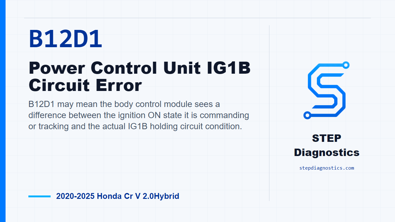
B12D1 may mean the body control module sees a difference between the ignition ON state it is commanding or tracking and the actual IG1B holding circuit condition.
What the vehicle may do
- The vehicle may have power mode or ignition-state complaints.
- The code may set with limited obvious symptoms.
- The concern can be related to how the IG1B power control path responds.
Possible fault areas
- Aftermarket accessories may affect the circuit.
- The IG1-B signal or IG1 coil wiring can be possible fault areas.
- The body control module can be involved.
- Other related components or the IG1B relay circuit may be involved.
Diagnostic path
Code overview and setup
On this 2020 to 2025 Honda CR-V Hybrid, B12D1 is a power control unit IG1B circuit error in the keyless access power control unit system. In plain terms, the body control module may be seeing a mismatch between the ignition ON command it believes it has made and what the IG1B holding circuit is actually doing. The vehicle may have power mode or ignition-state complaints, or it may simply store the code. Possible fault areas can include added accessories, the IG1-B signal or IG1 coil circuits, related control components, or the IG1B relay circuit. Start with the basic system checks. If other codes are present, check what they mean first, because network or body-system codes can change the order of diagnosis. Also confirm there are no aftermarket accessories tied into this area before you start testing the circuit.
Reproduce the operating conditions
Next, run the confirmation routine for B12D1. Turn the vehicle to ON mode and wait for at least 10 seconds. Then turn the vehicle to OFF, LOCK mode, and wait for at least 5 seconds. Keep this confirmation step separate from the circuit testing. It is there to reproduce the condition and give you a clean way to come back and verify whether the fault is still present after diagnosis.
Prepare for IG1-B signal and IG1 coil circuit checks
For the IG1-B signal and IG1 coil positive circuit inspection, power down as required for connector work, then disconnect under-dash fuse and relay box connector D, the 16-pin connector. After that, disconnect body control module connector C, the 66-pin connector. With those connectors disconnected, the circuit checks are made with ignition mode OFF.
Check the open circuits first
With the connectors still disconnected and IG mode OFF, check the IG1-B signal circuit for an open. A normal result is less than 1 Ω. Then check the IG1 coil positive circuit for an open the same way. That circuit also needs to be less than 1 Ω. If either check is abnormal, treat it as a circuit problem in that path before moving deeper into the diagnosis.
Check for short to ground
After the open checks, use the normal open-and-shorted-wire inspection approach for the short check. With IG mode OFF, inspect the IG1-B signal circuit for a short to ground. The normal result is more than 1 MΩ. If that result is abnormal, stay with the wiring diagnosis for that circuit instead of jumping ahead.
Check the body control module by substitution
If the circuit checks do not identify the fault, the next step is the body control module inspection. There is no direct test method given for this item, so the check is done by installing a known-good body control module and trying to reproduce the failure. If the failure is reproduced, the problem is still in other related components. If the symptom or B12D1 goes away with the known-good module installed, the body control module is considered faulty.
Final circuit conclusion and verification
If the other inspection items all indicate normal, the remaining conclusion is a problem with the IG1B relay circuit. Keep the logic in order: confirm the code, inspect the IG1-B signal and IG1 coil circuits, use the known-good module check when the circuit tests do not find it, and only then land on the remaining IG1B relay circuit. For verification, return to the same confirmation routine and confirm the code stays gone. The takeaway is simple: B12D1 is a command-versus-response problem in the IG1B power control path, so prove the wiring first, then the module check, then the remaining relay circuit. For more diagnostic training, visit stepdiagnostics.com.
Final check
B12D1 is often approached as a command-versus-response circuit diagnosis: confirm the condition, prove the wiring, then evaluate the remaining control and relay-side possibilities in order.
For more guided automotive diagnostics, visit STEP Diagnostics.