What this code means
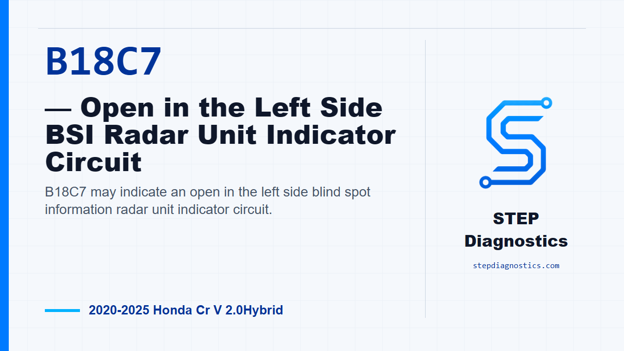
B18C7 may indicate an open in the left side blind spot information radar unit indicator circuit.
What the vehicle may do
- The vehicle may display a blind spot information warning.
- The left side blind spot alert indicator may not behave normally.
- The system may store the fault even when the driver does not notice a clear symptom.
Possible fault areas
- Possible left BSI alert indicator issue.
- Possible wiring, connector, or ground-side circuit issue.
- Possible left side BSI radar unit issue after related circuit checks are normal.
Diagnostic path
Opening and code meaning
On this 2020 to 2025 Honda CR-V Hybrid, B18C7 points to an open in the left side blind spot information radar unit indicator circuit. In plain terms, the radar unit is watching the indicator circuit, and when the indicator is commanded on or off, the circuit voltage may be outside the normal range. The driver may notice a blind spot information warning, an indicator that does not behave normally, or the system may set a fault without an obvious driving symptom. Possible fault areas can include the left BSI alert indicator, the indicator circuit wiring or connectors, ground side of the circuit, or the left side BSI radar unit itself. Start with the basic system checks, then follow a structured electrical diagnostic approach instead of jumping straight to a part.
Reproduce the monitor condition
First, reproduce the operating condition for the code. Turn the vehicle to the ON mode and wait for at least 5 seconds. That is the monitor gate for this diagnostic path, so keep verification separate from the circuit testing and use this same condition when you need to confirm whether B18C7 returns.
Indicator circuit simulation check
Next, check the left BSI alert indicator side of the circuit. Disconnect the left BSI alert indicator 2P connector. Then jump terminals No. 1 and No. 2 at that connector with a jumper wire. Turn the vehicle back to the ON mode. If the test behaves normally, B18C7 changes to the companion indicator-circuit fault, and that points to a problem with the left BSI alert indicator. If it does not behave normally, continue looking at the related circuit components rather than condemning the indicator from this check alone.
Open-wire inspection
Now move to the open-wire inspection for the BSI_L_IND and ground circuits. Disconnect the left BSI alert indicator 2P connector and disconnect the left side BSI radar unit 6P connector. Perform the open-wire inspection at the specified circuit points. With the inspection state OFF, the BSI_L_IND circuit should show less than 1 Ω, and the ground circuit should also show less than 1 Ω. If either side is abnormal, treat that as a circuit problem. If the exact connector cavity or test point is not clearly identified at the vehicle, pause and recheck the connector identification before probing; do not guess on terminal locations.
Radar unit judgment and verification
There is no direct component test given for the left side BSI radar unit itself, so this diagnosis works by proving the related parts of the circuit first. If the left BSI alert indicator check and the open-wire checks are normal, the remaining left side BSI radar unit is judged to be the cause. After any correction, verify the repair separately by turning the vehicle to the ON mode, waiting at least 5 seconds, and confirming B18C7 stays gone.
Takeaway and CTA
The takeaway on B18C7 is to simulate the indicator circuit first, prove the BSI_L_IND and ground wiring with a low-resistance open-wire check, and only judge the left side radar unit after the related circuit checks pass. For more diagnostic training, visit stepdiagnostics.com.
Final check
B18C7 is often approached as an electrical circuit diagnosis: simulate the indicator circuit, check the indicator and wiring paths, then judge the radar unit only after the related checks pass.
For more guided automotive diagnostics, visit STEP Diagnostics.