What this code means
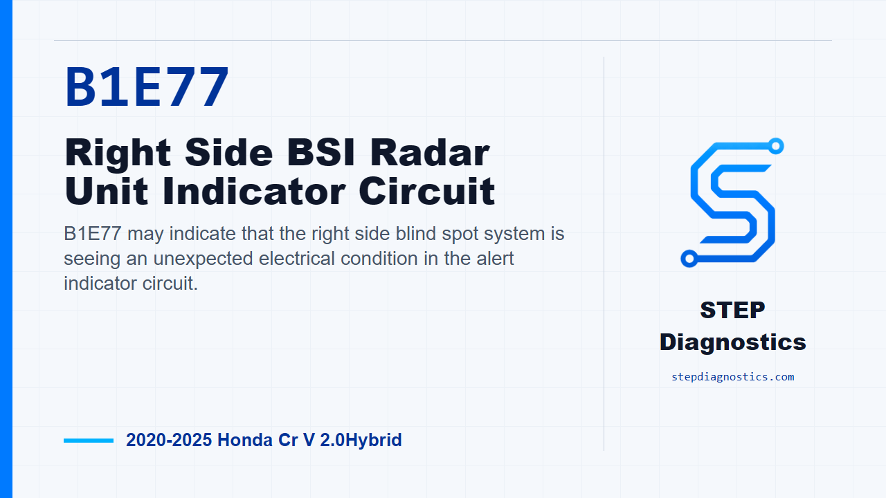
B1E77 may indicate that the right side blind spot system is seeing an unexpected electrical condition in the alert indicator circuit.
What the vehicle may do
- The blind spot alert may not operate normally on the right side.
- A blind spot system warning may be displayed or stored.
- The concern may be intermittent if the circuit condition changes with connector movement or vibration.
Possible fault areas
- The right BSI alert indicator may be involved.
- The indicator circuit wiring or ground path may be involved.
- The right side BSI radar unit may be involved after related circuit checks are normal.
Diagnostic path
Open on B1E77
On this CR-V Hybrid, B1E77 points us toward the right side Blind Spot Information radar unit indicator circuit. In plain terms, the radar unit may be seeing the right alert indicator circuit voltage outside the range it expects when that indicator is commanded on or off. The driver may notice the blind spot alert not behaving normally, or the system may flag a warning. Broadly, keep the possible fault areas to the right alert indicator, the indicator wiring and ground side of the circuit, and the right side BSI radar unit. Start with the basic system checks and follow a structured diagnostic approach before you get into connector testing.
Set up the confirmation
To confirm the fault path for B1E77, turn the vehicle to the ON mode and wait for at least 5 seconds. Treat that as the monitor gate for this check. You are not trying to diagnose every blind spot code here; keep the focus on whether this right indicator circuit fault is active under the operating condition that lets the system make its decision.
Simulate the right alert indicator circuit
Next, move to the right BSI alert indicator check. Disconnect the right BSI alert indicator connector, the 2-pin connector, then connect terminals No. 1 and No. 2 together with a jumper wire. Turn the vehicle back to ON mode. If the circuit reacts normally, B1E77 should change into the companion indicator-circuit code. When that happens, the diagnostic direction is the right BSI alert indicator itself. If it does not react that way, do not condemn the indicator; continue into the related circuit checks.
Check the indicator and ground circuits for opens
If the simulated indicator check is abnormal, disconnect the right BSI alert indicator connector and the right side BSI radar unit connector, the 6-pin connector. Then check the BSI_R_IND side and the ground side for an open. A normal result on each of those checks is less than 1 Ω. If either side is abnormal, stay with the circuit problem. Do not jump ahead to the radar unit until the wiring path has passed. Also, make sure you can positively identify the correct terminals before measuring; if the terminal locations are not clear, pause and do not guess at the connector pins.
Use the related-component logic before blaming the radar unit
There is no direct standalone test for the component itself in this path, so the diagnosis works by checking the related pieces first. If the alert indicator check does not isolate the indicator, and the BSI_R_IND and ground circuit checks are normal, the remaining fault area is the right side BSI radar unit. That is the point where the diagnostic logic identifies a problem with the right side BSI radar unit, not before.
Close and verify
Keep the order clean: confirm B1E77, simulate the indicator circuit, check the open-wire paths, and only then decide whether the remaining fault area is the right side BSI radar unit. After the fault area has been corrected, verify under the same ON-mode confirmation condition and make sure B1E77 does not return. The takeaway is simple: this code is diagnosed by proving the indicator circuit response first, not by guessing at the radar unit. For more diagnostic training, visit stepdiagnostics.com.
Final check
B1E77 is best approached as an electrical circuit diagnosis where the indicator response and wiring checks guide the next step.
For more guided automotive diagnostics, visit STEP Diagnostics.