Applicability basis: The STEP vehicle catalog groups these guides under the 2019-2024 Ram 1500DT 5.7L HEMI Gas application. Detailed system-operation and diagnostic evidence for this overview was verified on the exact 2024 Ram 1500 Truck 4WD 5.7L eTorque MHEV application. Exact sensor locations, module routing, circuit identifiers, thresholds, test values, scan-tool functions, and service procedures can vary by model year, drivetrain, equipment, and calibration; use current service information for the truck being repaired.
What the air-temperature sensing system does
The truck uses two related but distinct measurements in the DTC guides linked below:
- ambient air temperature (AAT) represents the air around the vehicle; and
- intake air temperature (IAT) represents the air entering the engine.
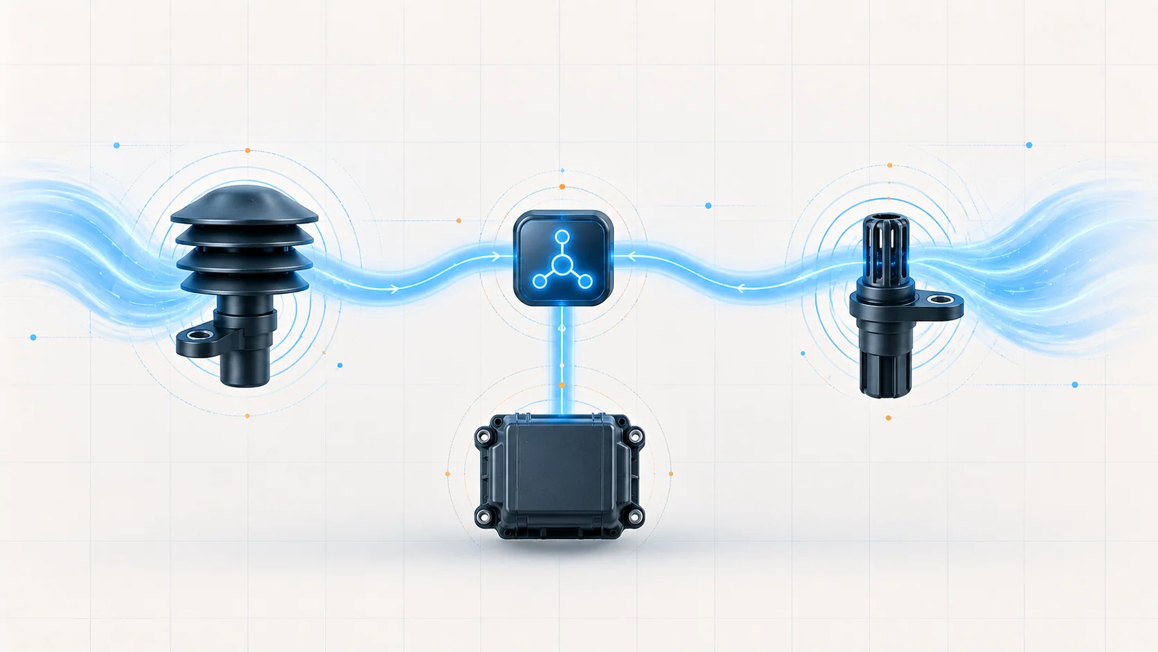
AAT supplies outside-air context for body-side functions and for powertrain plausibility decisions. IAT helps the powertrain control module (PCM) interpret incoming-air density and operating conditions. They measure different environments and follow different diagnostic paths, so one reading cannot stand in for the other.
A temperature-sensor DTC means that a monitored electrical signal or comparison failed a calibrated test. It does not prove that the actual air is unusually hot or cold, and it does not automatically condemn the sensor.
How the system turns temperature into data
A changing resistance becomes a temperature value
Both sensing paths use temperature-sensitive resistance. The reading module observes a voltage produced by the sensor circuit and converts it into a temperature estimate. Because the estimate depends on the complete circuit, an open wire, excess resistance, short to ground, short to voltage, poor terminal contact, damaged return path, or failed sensor can imitate an extreme temperature.
The AAT value travels through the vehicle network
On the verified application, the AAT sensor is a two-wire input read on the body side of the vehicle. That module converts the analog signal into data and broadcasts the value across the vehicle network. The PCM receives the ambient value from the network and applies the powertrain rationality monitor.
The exact sensor location and reading module can vary with configuration. Follow the current wiring diagram instead of assuming that the AAT sensor is connected directly to the PCM.
The PCM reads IAT directly as an engine input
The IAT path uses a signal circuit and a filtered sensor-ground circuit supplied and monitored by the PCM. The PCM converts the signal voltage into a temperature value. Actual IAT can differ from ambient temperature because of heat soak, airflow, engine load, and recent operating history.
Cold-soak comparisons test plausibility
After a sufficient soak, AAT, IAT, and engine coolant temperature should start in a reasonably related region. The strategy can compare those readings to decide whether one value is implausible. This is a contextual comparison, not a rule that all three values must match once the engine is running.
What the related DTCs tell you
| DTC | Diagnostic direction | What must be proved |
|---|---|---|
| P0072 | AAT signal is electrically at the low side of its monitored range | Whether the sensor circuit, connector, sensor, or reading module explains the value |
| P0073 | AAT signal is electrically at the high side of its monitored range | Whether an open/high-resistance path, short to voltage, connector fault, sensor, or reading module explains the value |
| P0113 | IAT Sensor 1 failed its high-circuit monitor | Whether the IAT signal, sensor ground, connector, sensor, or PCM is responsible in the directed order |
The words “low” and “high” describe the monitored electrical condition. They do not describe confirmed outside-air temperature and they are not replacement instructions. P0072 and P0073 concern the ambient path; P0113 concerns the intake path.
What the driver or technician may notice
Possible observations include:
- a malfunction indicator lamp with little or no drivability complaint;
- an outside-temperature display that is implausible, fixed, delayed, or intermittent;
- an IAT value that appears implausibly hot or cold for the soak and operating condition;
- a fault that begins after front-end, mirror, door, intake, air-cleaner, harness, battery, or module work; or
- several temperature readings that disagree after a genuine cold soak.
Symptoms are clues, not proofs. Sun load, road heat, slow speed, sensor placement, a hot restart, and underhood heat soak can create legitimate differences.
Common failure categories
Open or high-resistance paths
A broken conductor, weak splice, backed-out terminal, corrosion, damaged connector lock, or partially separated wire can push a reading toward an electrical extreme. Intermittent opens may respond to vibration or temperature even when the harness looks intact.
Shorts and cross-circuit faults
Rubbed insulation, pinched wiring, water intrusion, or incorrect previous probing can pull a signal toward ground or voltage. Isolate connected modules and components exactly as directed before resistance or short testing so a normal internal path is not mistaken for a harness fault.
Sensor-ground and connector faults
The IAT signal is meaningful only relative to its correct sensor ground. Excess resistance or an open in that return can distort the value. Loose engagement, spread terminals, pushed-back pins, damaged seals, corrosion, and poor terminal tension can cause the same complaint.
Sensor, module, or network responsibility
The sensing element can fail, but sensor replacement comes after the circuit is proved. A body-side reader, network path, or PCM can also be responsible. Resolve active voltage and communication faults first, and prove powers, grounds, circuits, terminals, and response before considering controller replacement or programming.
A system-first diagnostic strategy
1. Preserve the original evidence
Confirm the exact year, engine, drivetrain, equipment, calibration, and recent work. Save the complete module scan, active/pending/history DTCs, failure records, AAT, IAT, coolant temperature, system voltage, and operating conditions before clearing anything.
2. Check relationships before replacing parts
Look for voltage, communication, reference, or multiple temperature-sensor codes. A shared power, ground, connector, module, or network problem can produce more than one implausible reading.
3. Compare temperatures only under valid conditions
After a true cold soak, compare AAT, IAT, and coolant temperature with the truck's environment. Do not condemn a sensor from a hot restart or a sun-heated parked vehicle. After startup, watch whether each value changes in a physically believable direction.
4. Separate active from intermittent faults
For an active code, follow the current directed circuit test. For an intermittent code, use the stored conditions to reproduce it safely while inspecting connectors and gently stressing the relevant harness. A scan value that reacts to harness movement is evidence, but the precise terminal or conductor still must be isolated.
5. Inspect before disturbing the system
Check recent-work areas, routing, retainers, sharp edges, heat exposure, water entry, locks, seals, and terminal position. Preserve routing before disassembly and avoid creating a second fault with oversized probes.
6. Prove signal and return paths
Use the exact wiring diagram, terminal-safe adapters, and specified test conditions. Check for opens, excessive resistance, shorts to ground, shorts to voltage, and cross-circuit contact in the order directed by current service information. On the verified 2024 target, the procedure prohibits direct probing at the PCM harness connector and requires the specified diagnostic adapter. For any truck in the grouped range, use the terminal-safe method specified by its current service information.
7. Prove module response before assigning responsibility
A directed substitution or fused-jumper test can show whether the reading module recognizes a known circuit state. It proves the response of the path; it is not permission to leave a jumper installed. Replace a sensor only when circuit integrity and response evidence support it. Consider a controller only after its connections, powers, grounds, communication, and related circuits are proven.
8. Verify the complete repair
Restore routing, seals, locks, retainers, intake joints, and removed components. Clear codes when directed, repeat the relevant monitor or operating condition, and confirm that the DTC does not return as pending or confirmed. Recheck temperature plausibility after an appropriate soak and verify the original display or drivability complaint.
A cleared warning lamp or one plausible scan value during a brief idle is not repair verification.
Repair categories
The evidence may support:
- signal, sensor-ground, splice, terminal, connector, seal, or harness repair;
- AAT sensor replacement after the ambient circuit and reader response are proved;
- IAT sensor replacement after the IAT circuit and PCM response are proved;
- correction of a disturbed or damaged sensor installation;
- body-side or powertrain controller repair, replacement, and programming only after all prerequisites are met; or
- correction of a shared voltage, ground, or communication fault.
Do not choose a repair from the code title alone.
Safety and service cautions
Running-engine tests place the technician near the fan, belts, pulleys, hot exhaust parts, and other moving or hot components. Secure clothing, hair, leads, and tools. Never measure resistance on an energized circuit, and turn the ignition off before disconnecting modules when the procedure requires it.
Use terminal-safe adapters and restore weather seals and retainers. The eTorque label identifies the verified configuration; this overview is not authorization to open, disconnect, or test the 48-volt eTorque system. Follow the current high-voltage precautions whenever work enters that system's scope.
Final takeaway
The 2019-2024 Ram 1500DT 5.7L HEMI Gas air-temperature system uses separate ambient and intake measurements. The body side reads and shares AAT, while the PCM directly evaluates IAT and uses temperature context for rationality checks.
P0072, P0073, and P0113 identify failed circuit checks, not automatically failed sensors or confirmed weather extremes. Preserve the original evidence, compare values only under valid conditions, prove signal and return paths, respect the network and module boundaries, and verify the repair only after the relevant monitor reruns and the original complaint is resolved.