Oil-pressure monitoring connects two different questions: does the engine have adequate oil pressure, and can the powertrain control module trust the pressure sensor's electrical signal? On the 2019–2024 Ram 1500DT 5.7 HEMI gas engine, confusing those questions can lead to an unnecessary sensor replacement—or to overlooking a lubrication problem.
This is an educational overview for mechanics, not a replacement for the service procedure. The year range identifies STEP's Ram 1500DT 5.7 HEMI vehicle library; it does not include the separately cataloged 1500 Classic. The source checks include an early non-eTorque configuration and a later eTorque configuration. Match the actual model year, engine, drivetrain, eTorque equipment and PCM variant before using pressure specifications, monitor conditions, wiring, test adapters or repair instructions. The applicable service information controls those details.
What the system does
The pressure sensor provides the PCM with information about engine oil pressure. Its purpose is measurement and fault detection, not proof that oil is reaching every lubricated part correctly. Oil level, oil condition and measured pressure are related checks, but none is interchangeable with the others.
The sensor and its wiring form the electrical side of the system. The oil's condition and the engine's mechanical lubrication condition form the physical side. A diagnostic trouble code can arise from either side, depending on which behavior the monitor detected.
How the pressure signal reaches the PCM
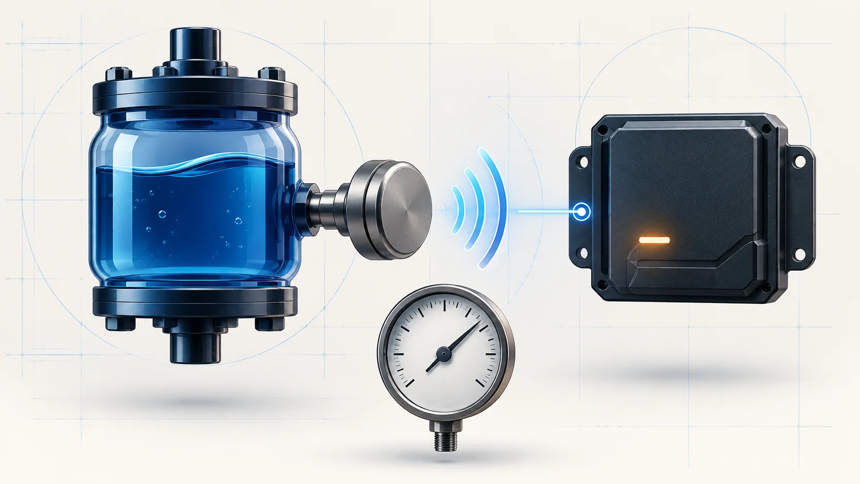
The sensor uses a reference supply from the PCM, a sensor return or ground, and a signal circuit back to the PCM. It returns a voltage associated with oil pressure. The controller evaluates that information under the conditions assigned to the applicable diagnostic monitor.
The signal circuit's internal bias is not universal. PCM hardware can use different pull-up or pull-down arrangements, so an unplugged-sensor voltage or an improvised jumper response is not a safe cross-year shortcut. Identify the correct circuit and controller-specific test before drawing conclusions from a meter reading.
A scan-tool pressure value is still information derived from the sensing path. A mechanical gauge check, performed with the specified equipment and operating conditions, provides a separate pressure measurement. If the sensing path is faulty, a plausible-looking scan value alone cannot establish actual engine oil pressure.
Performance and circuit faults are different starting points
P0521 — Engine Oil Pressure Sensor Performance concerns pressure information that fails the applicable performance check. The source diagnostic path considers oil level, oil history and viscosity, deteriorated or contaminated oil, actual pressure and mechanical condition before progressing through the sensor circuits. It is not a command to replace the sensor.
P0522 — Engine Oil Pressure Sensor Circuit Low concerns a low electrical signal. Reference-supply faults, a signal short to ground or sensor return, connector problems and sensor or controller faults belong in that investigation. A circuit-low code is not, by itself, a mechanical-gauge result showing low oil pressure.
Both categories can illuminate the malfunction indicator lamp. The truck may otherwise seem normal, or pressure information may be abnormal. Neither normal drivability nor a code description settles the physical lubrication question.
Failure categories to keep separate
Oil-related concerns include an incorrect level, unsuitable viscosity, neglected service, deteriorated oil and contamination by coolant or fuel. Actual low pressure or mechanical conditions may require an engine-side investigation rather than electrical repair.
Electrical concerns include a missing or faulty reference supply, unwanted connections between circuits, open circuits and excessive resistance. Loose locks, damaged or spread terminals, corrosion, water intrusion and poor terminal contact can disturb the signal without making the sensor itself the failed part.
The sensor can also fail. The PCM is a later possibility, after the applicable circuit, connection and component checks—not the first conclusion from an unusual pressure reading. Consult relevant service bulletins without assuming that one bulletin applies to every truck in the library.
A practical diagnostic strategy
Start with safety and the complaint. If pressure is genuinely absent or inadequate, do not keep running the engine merely to reproduce a code. The source mechanical-pressure test explicitly calls for shutdown when no pressure is present at idle. Do not use the absence of a warning lamp as permission to ignore evidence of a lubrication fault.
Save the all-module scan report, related DTCs and recorded operating data before clearing anything. Establish whether the fault is active or intermittent and what conditions accompanied it. Diagnose relevant reference-supply codes when the applicable P0522 path directs you to do so; do not treat every stored code as an independent failed sensor.
For a performance complaint, establish the oil and mechanical condition early. Check the level using the applicable method, review the service history, and verify the oil specification and condition. Where actual pressure needs confirmation, use the vehicle-specific gauge procedure and its temperature and engine-speed requirements. This overview intentionally supplies no universal pressure limit.
For an electrical complaint, confirm the correct wiring and test branch, then inspect connector seating, locks and terminals. Separate the reference, return and signal circuits in your reasoning. Test for the specific open, resistance or short condition identified by the procedure rather than changing parts until a reading improves.
Continuity and resistance checks require the ignition off and the circuit isolated as directed. Protect PCM terminals: use the prescribed diagnostic adapter and access method instead of pushing probes into the PCM harness connector. Account for test-lead and adapter resistance when interpreting an allowed resistance test. Do not perform a powered jumper test from a generic description of the circuit.
If the fault does not return under the applicable conditions, follow the intermittent diagnostic path. A single clean scan after clearing is not proof that the original problem has been repaired.
Repair categories and verification
The repair follows the demonstrated fault: correct an oil-level or service problem, investigate contamination or confirmed mechanical pressure loss, repair damaged wiring or terminals, restore a proper connector connection, or replace a sensor when the applicable test supports it. Correcting the oil does not excuse leaving a demonstrated circuit fault unresolved, and replacing the sensor does not establish that mechanical pressure is satisfactory.
Controller replacement and programming belong only at the supported end of the applicable diagnostic path. They are not substitutes for verifying the reference supply, return, signal and related connections.
After repair, restore every disturbed connector and test connection correctly. Follow the specified powertrain verification procedure and reproduce the original monitor conditions only when engine operation is safe. Recheck DTCs and pressure evidence as appropriate to the original fault. Document both what failed and what now passes; code clearing alone is not the final check.
Safety and service boundaries
Oil-pressure testing can involve hot engine oil and running-engine hazards. Use suitable protective equipment, keep clear of moving parts, and follow the specified installation and removal procedure for the pressure-test connection. Do not loosen a pressure connection with the engine running. Stop if the test setup leaks or pressure evidence makes continued operation unsafe.
Use the electrical and eTorque safety procedures applicable to the actual vehicle before the work requires them. This article does not provide an eTorque disable sequence, connector pinout, sensor location or interchangeable controller test. Even the linked DTC guides must be checked against the exact service information for the truck being repaired.
The useful distinction is simple: establish whether the oil-pressure problem is physical, electrical, or both. Use P0521 and P0522 to select the right diagnostic path, not to select a replacement part.