
Mechanic Guides
Automotive Oscilloscope Aliasing: Check Sampling Before Calling a Signal Slow
Check acquisition duration and sample rate before diagnosing an unexpectedly slow automotive waveform. Includes a capture comparison record.
Published · 5 min read
Quick answer
Aliasing can make an undersampled signal appear slower or misleadingly flat. Preserve the original capture, then acquire a new record with suitable sampling settings. Zooming an old record cannot recover samples that were never acquired.
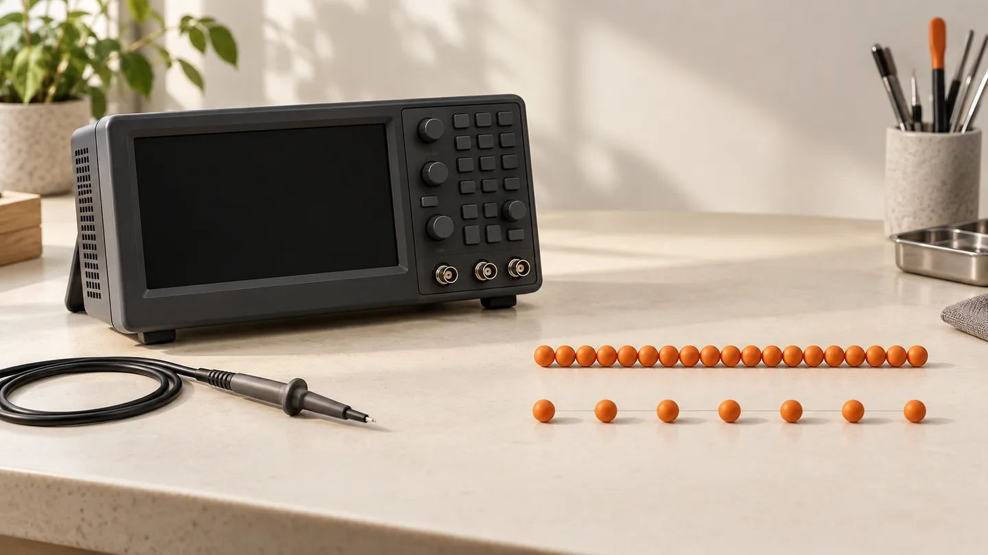
An unexpectedly slow waveform can send a technician toward the wrong component. Before interpreting the apparent frequency as vehicle behavior, check how the scope acquired the record. A plausible-looking trace is not proof that the acquisition captured the signal faithfully.
This guide helps professional technicians review sampling on low-voltage automotive captures. Connection points, probe ratings, grounding and vehicle-specific expectations must still come from the equipment and service instructions. It is not a connection procedure for ignition or high-voltage systems.
What aliasing means
A digital scope records samples of a changing signal. If sampling is insufficient, the displayed record can represent the wrong apparent frequency. A rapidly changing input may look slower; particular sampling relationships can even make it appear flat.
The practical consequence is simple: “the trace looks slow” and “the vehicle signal is slow” are different claims. The second needs a capture whose acquisition settings are suitable for the signal and the question being asked.
Duration and detail are separate needs
The timebase determines how much time is represented across the waveform display. A long capture can be useful for keeping the surrounding event in context. But the number and spacing of acquired samples also matter. Check the instrument's actual sampling information after choosing duration and other acquisition settings.
Do not treat a scope's advertised maximum sample rate as the rate used by every saved capture. Record the setting or acquisition information associated with the file you intend to interpret. Consult the instrument instructions when the relationship between duration, memory and active acquisition configuration is unclear.
The correct choice depends on the feature you need to resolve. Finding a broad operating transition and examining a short pulse are different questions. Write the question before changing the controls.
A capture comparison that tests the measurement
Save the original record first. Label the test points, operating state, duration, actual sample rate or interval, probe scaling and trigger. Keep it as evidence of what initially caused concern.
Next make a fresh acquisition with a shorter duration or another supported setting that increases available sampling detail. Verify the resulting sample information rather than assuming the control change had the intended effect. Keep vehicle conditions as comparable as practical, and record any changes in engine speed or commanded state.
Compare the new record with the original. A large change in apparent frequency or shape after an acquisition change raises concern about the original measurement. It does not by itself prove aliasing: the vehicle may have changed state, or another setup difference may explain the change. Reproduce the comparison under controlled conditions before drawing a component conclusion.
If a long context record is still needed, check whether the scope supports sufficient record length for that duration at the required sampling settings. Follow its documented limits. There is no single sample-rate setting that covers every automotive waveform and every diagnostic question.
Acquisition is different from zoom
Zoom can make existing samples easier to inspect. It cannot add the missing samples from an earlier acquisition. If the original record lacks the needed detail, acquire a new record; enlarging the old trace is not a substitute.
Likewise, a stable-looking display is useful for viewing but is not a general guarantee of measurement validity. Check the setup and the expected signal, not just the visual smoothness of the line.
A fictional diagnostic example
A shop saves a long-duration capture and sees a slow repeating pattern. Before recommending a sensor, the technician saves the setup and repeats the measurement with a shorter acquisition and verified sampling information. The apparent pattern changes substantially.
The case note now says: “Original frequency interpretation not validated. Repeat capture differs after acquisition change; operating conditions must be matched and sampling checked before judging the sensor.” That is a useful result even before a failed part is identified. It prevents an uncertain measurement from becoming a confident repair recommendation.
What to hand to the next technician
Attach both native records where available, not only screenshots. Record the acquisition settings, operating conditions, comparison result and unresolved question. The downloadable worksheet keeps those fields together without imposing a generic pass/fail frequency.
For a separate setting that changes what voltage information is shown, read AC versus DC coupling. For choosing the instrument, see oscilloscope versus multimeter.
STEP is in Early Access. To discuss how your shop organizes captures, observations and follow-up checks, request STEP Early Access.