
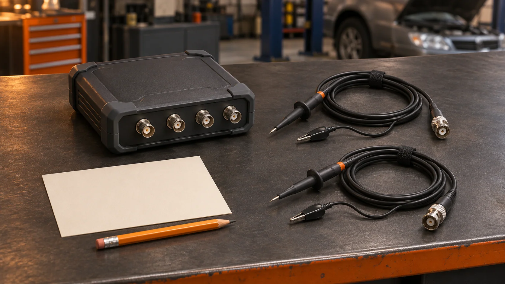
A saved waveform can show what a voltage did while hiding a more basic detail: where each channel's return lead was connected. Before adding a second channel, identify the input architecture of the actual scope. Two clips that look separate may be electrically connected inside the instrument.
Find the return topology in the manual
In a common-ground scope, the indicated channel returns share an electrical reference. Pico's older 3000 Automotive manual explains that the marked BNC outer shells are connected together. It warns that applying a voltage between those returns can cause substantial current and damage. Attaching shared returns to points at different potentials can therefore join those circuit points through the test equipment.
This is a hardware question, not a channel-count question. Pico's 4823 product description identifies a common-ground design despite its eight channels. Do not infer independent inputs from the number of sockets or from the word automotive.
Start the connection record with the exact scope model, probe or lead set, and manual section. Write whether the relevant returns are shared, independently referenced within stated limits, or unresolved. If the documentation does not settle the question, resolve it with the manufacturer before connecting.
Keep channel common and protective earth separate
The connection between channel returns is one relationship. Their relationship to the computer, chassis and protective earth is another. A battery-powered computer or USB connection alone does not establish the isolation of the complete setup.
The Pico 4x23/4x25 safety guide distinguishes a measurement-ground terminal from protective safety earth. It also lists signal-input and common-mode limits separately. The allowed difference between the signal and its return is not automatically the allowed difference between that return and another reference.
Tektronix's grounding brief describes the traditional bench-scope arrangement in which signal common is connected to protective earth. It warns against defeating that protective grounding to float the instrument. Never remove a protective-earth connection to make a proposed vehicle measurement possible. Use the exact instrument and accessory instructions to resolve the setup.
A floating input still has boundaries
Pico's floating-input explanation contrasts named 4x25/4x25A models with common-ground designs. Their channel references can differ within specified limits. The same article cautions that the negative input has its own voltage and loading restrictions.
Treat floating as a model-specific capability, not permission to place a return anywhere. Check the complete expected signal, including transients, against every applicable instrument and accessory limit. This guide concerns planning conventional low-voltage vehicle measurements; it supplies no mains, traction-battery or high-energy connection procedure.
A math channel does not alter the wiring. Subtracting two traces cannot electrically separate returns that the scope already joins. If an approved measurement uses two channels and subtraction, both physical connections still have to satisfy the hardware instructions. Record the raw channels alongside the calculated result.
Make a connection-reference card
Use the original downloadable card before connecting, then keep the completed record with the capture. Give each active channel a separate entry:
- Signal point and return point, identified by the applicable diagram or a clear sketch.
- Scope, accessory and manual reference; which returns are electrically common.
- Relevant signal and common-mode limits and their source.
- Computer, charger, vehicle support equipment and other connected instruments that may affect the reference arrangement.
- Selected probe scaling, coupling, range and math operation.
- Original file, operating state and any unresolved setup question.
Suppose one technician documents a signal relative to battery negative, while the next proposes measuring directly across a component. Those are different connection plans. The first record does not authorize moving the return for the second. Recheck the intended measurement against the exact hardware and applicable procedure.
Keep coupling and probe attenuation in the same setup record, but resolve return topology first. Attach the card to the diagnostic report so another technician can reconstruct the observation.
STEP is inviting shops into Early Access. Share how your team keeps connection context and the next diagnostic check attached to a saved case.