
Mechanic Guides
Automotive Oscilloscope Probe Attenuation: Check the Ratio Before Trusting Voltage
Verify automotive scope probe attenuation, channel scaling and measurement references before interpreting voltage. Includes a downloadable setup record.
Published · 5 min read
Quick answer
Match the physical probe or attenuator ratio to the channel display setting, then verify the setup on a suitable known signal. Software scaling does not add hardware protection. Do not multiply the result again if the instrument already corrects it.
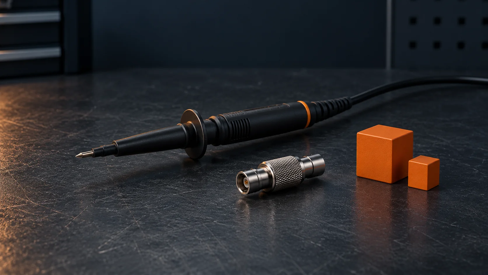
A waveform can have the expected shape and still show the wrong voltage. Before diagnosing a weak supply or an excessive signal, compare the physical probe or attenuator ratio with the channel scaling. A 10:1 attenuator reduces the voltage reaching the scope input; a matching software setting restores the displayed value to the probe-tip scale. Do not multiply a reading again when the instrument already applies that correction.
Separate the hardware from the display
The physical accessory changes the signal delivered to the instrument. The channel setting tells the display how to interpret that signal. Changing a menu setting does not install an attenuator or make an unsuitable connection safe.
For an ideal illustrative example, a 10 V signal through a 10:1 accessory produces 1 V at the scope input. With the channel configured correctly, the displayed measurement represents 10 V at the test point. With an uncorrected 1:1 display setting, it represents 1 V instead. These numbers explain scaling; they are not specifications for any vehicle circuit.
Record the complete measurement chain
Before connecting to a vehicle, identify the scope input, lead, probe or attenuator, and any adapters. Check their compatibility and published limits, including the input configuration required by the accessory. The ratio alone is not a voltage rating. A generic 10:1 probe is not automatically suitable for ignition, hybrid or EV high-voltage measurements.
Keep the measurement reference explicit. A passive probe or inline attenuator does not provide isolation merely because it divides the voltage. Follow the instrument and vehicle procedures for ground connections; do not assume that two scope ground connections can be placed at different circuit potentials.
Verify scaling on a suitable known signal
Use the manufacturer's recommended verification method before relying on a questionable reading. Confirm the physical switch or accessory marking and the channel configuration. If the scope recognizes the accessory automatically, verify the result instead of adding a second manual correction.
Save the ratio and input settings with the capture. A screenshot that omits those details can leave the next technician unable to determine whether a voltage discrepancy belongs to the vehicle or the setup.
Compensation is a separate check
For compatible passive probes, compensation adjusts the probe's frequency response. It is different from choosing the displayed attenuation factor. Follow the probe and scope instructions using the specified reference signal. Do not adjust compensation to force an unfamiliar vehicle waveform into an expected shape.
A higher attenuation ratio also reduces the signal reaching the input. That can make a small signal harder to resolve. Select the complete measurement setup for the signal and required detail, rather than assuming that a larger ratio is always better.
A capture record another technician can check
Record these fields beside the original acquisition, rather than leaving the next technician to infer the setup from a screenshot:
- Vehicle, circuit, test point and operating condition.
- Scope model, channel, input configuration and measurement reference.
- Probe or attenuator identification, physical ratio and switch position.
- Configured channel ratio and whether correction was automatic or manual.
- Applicable accessory and instrument limits, checked against the intended connection.
- Verification method, expected reference value and displayed result.
- Capture filename, observed symptom and unanswered diagnostic question.
Fictional setup example: a technician checks a permitted reference signal through a 10:1 accessory, but the channel remains set to 1:1. The displayed voltage is one tenth of the expected probe-tip value. After correcting the channel setting and verifying the reference again, the technician makes a new vehicle capture and records the change. The first capture is retained with a scaling-error note; it is not used as evidence of a weak vehicle supply. This example describes a setup error, not a vehicle test specification.
If the ratio and reference check agree but the trace still looks wrong, continue checking the acquisition settings. The AC versus DC coupling guide explains offset changes, while the aliasing guide addresses sampling. Neither problem is corrected merely by changing a probe ratio.
Before making a diagnostic decision
Confirm the accessory ratio, display correction, input configuration, measurement reference and applicable limits. Then compare the capture with vehicle-specific service information under the specified operating conditions. If a repeat capture with verified settings changes the voltage result, document the setup correction before replacing a component.
Use the downloadable measurement-chain record to preserve the confirmed setup and the next diagnostic question. STEP is in Early Access. Request early access if your shop wants to discuss organizing diagnostic evidence and next tests. This guide does not imply automatic oscilloscope integration or waveform interpretation by STEP.