
Mechanic Guides
Automotive Oscilloscope Probe Compensation: Check the Probe Before the Waveform
Check passive oscilloscope probe compensation before interpreting automotive waveforms. Separate reference verification from scaling and save a repeatable bench record.
Published · 4 min read
Quick answer
Verify a compatible adjustable passive probe against the instrument reference before interpreting vehicle waveforms. Compensation checks response; attenuation settings establish scaling.
Why check the probe before interpreting the capture?
A waveform is evidence from a measurement chain. Before interpreting an unexpected edge as a vehicle fault, establish that the probe and scope are ready for that measurement. Probe compensation is one check for a compatible adjustable passive voltage probe. It is not a repair adjustment and does not apply automatically to every automotive probe or lead.
This guide describes a bench verification workflow. Use the instructions for the actual probe and oscilloscope to identify compatibility, the reference connection and the adjustment method. Current clamps, active probes and differential probes can have different checks; do not assume they use this procedure.
What compensation changes
A passive probe's compensation adjustment matches its capacitive response to the scope input. Incorrect compensation can distort pulse shape and amplitude. On the specified square-wave reference, an undercompensated response can have a rounded leading region, while overcompensation can produce overshoot. Correct adjustment aims for the reference shape described by the manufacturer, including a flat pulse top.
That differs from probe attenuation. Attenuation settings tell the measurement system how to scale the signal. A correct displayed factor does not establish that the probe's response is properly compensated. Record these as separate checks.
Establish a known reference
Identify the probe, scope and input being used. Read the probe instructions before looking for an adjustment screw. If the combination is unsupported, or the probe has no user compensation adjustment, stop and find its specified verification method.
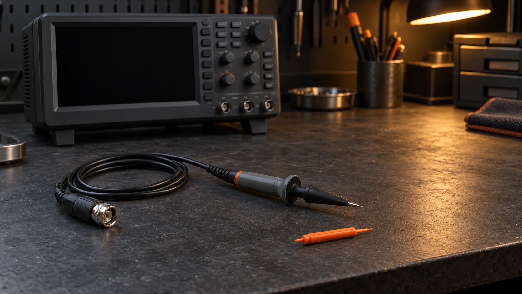
For an adjustable passive probe, use the manufacturer's reference output and prescribed connection. Follow the instructions for the reference ground and tool; a nonconductive adjustment tool is commonly specified. Perform this reference check before connecting to the vehicle.
Do not adjust compensation while watching an unfamiliar vehicle signal to make it look like an expected waveform. That removes the known reference from the decision and risks confusing a measurement-system problem with the behavior being investigated.
Make a repeatable bench record
Use a short record that another technician can reproduce:
- Probe identification and selected attenuation position.
- Scope identification, input channel and matching channel factor.
- Reference source and instrument procedure used.
- Initial reference appearance and whether an adjustment was needed.
- Final reference capture, date and any unresolved mismatch.
Check before first use and important measurements, and follow the manufacturer's recheck requirements when changing the scope or probe combination. Do not treat an old screenshot from a different instrument pairing as proof that the present pairing is ready.
Keep the reference capture separate from vehicle evidence. Labeling both files clearly prevents someone reviewing a repair order from treating a bench square wave as an engine or network measurement.
If the response will not settle correctly
Do not keep turning the adjustment to compensate for an unidentified problem. Recheck the documented pairing, settings and reference connection. If the prescribed response cannot be obtained, treat the probe-and-scope combination as unresolved and follow the instrument troubleshooting procedure before relying on it for the planned capture.
A successful compensation check is also limited evidence. It does not certify every probe characteristic, establish vehicle circuit safety, verify all scope calibration requirements or prove that a later waveform was acquired with suitable settings.
A shop handoff example
Consider a fictional handoff: a technician borrows a passive probe from another scope, captures an unusual pulse and sends only the vehicle screenshot. The next technician cannot tell whether the shape belongs to the circuit or the changed instrument pairing.
A stronger handoff adds the probe identity, scope input, attenuation settings and a saved reference check performed using the instrument instructions. The vehicle capture still needs its operating conditions and acquisition context, but one avoidable ambiguity has been addressed.
Use the downloadable record to keep that bench check with the job's measurement notes. For professional mechanics and independent shops exploring STEP, request Early Access.