
Mechanic Guides
DC Current Clamp Zero Check: Validate the Reading Before Chasing a Draw
Check clamp capability, zero, range and scaling before using a small current reading to make an automotive diagnostic decision.
Published · 5 min read
Quick answer
For DC current, follow the clamp manufacturer’s zero procedure with the jaws closed and no conductor inside. Confirm range, scaling and suitable accuracy. If the baseline is unstable, resolve the measurement problem before treating a small reading as vehicle current.
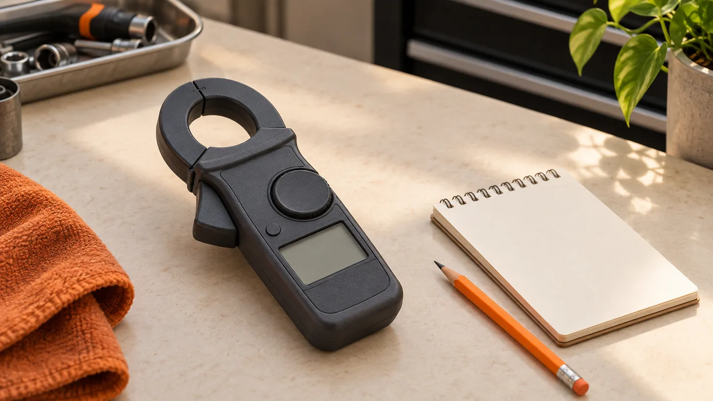
A small current reading can send a technician toward a long circuit-isolation job. First establish that the measuring setup can support that conclusion. A zero check is part of that preparation; it is not a substitute for the clamp’s accuracy specification or the vehicle’s test procedure.
This guide concerns measurement quality on conventional automotive low-voltage circuits. It does not authorize high-voltage testing, exposed-conductor work or a particular connection method. Use equipment ratings and the applicable service procedure to decide whether the planned test is appropriate.
Separate three questions
- Capability: does this clamp measure DC current in the range of interest?
- Setup: are the selected range and the receiving instrument’s scaling correct?
- Baseline: what does the instrument indicate under the manufacturer’s prescribed zero condition?
A display showing several decimal places does not establish that a small current is measured accurately. Check the complete measurement chain, including a separate meter or scope when a clamp produces a voltage output. Record the applicable accuracy and operating-condition limits instead of borrowing another tool’s specifications.
Establish zero before measuring
For a clamp that requires manual DC zeroing, follow its instructions, allow the indication to stabilize, and zero with closed jaws and no conductor inside. Do not press zero around a current-carrying cable to make an inconvenient reading disappear. That changes the reference used to interpret the result.
Controls differ between clamps. Some use automatic routines; others have a manual adjustment. If zero cannot be established, consult the exact manual. One manufacturer documents a jaw-opening and closing procedure for a particular clamp’s hysteresis behavior; that is not a universal repair for every probe.
Record the no-conductor indication before and after the approved zero routine. If the baseline continues to move, stop using the setup to support a small-current conclusion. Check the instrument’s condition, power supply and specified environment before repeating the test.
Preserve range and scaling information
An accessory clamp’s output can be expressed as voltage per unit of current. The selected clamp range and the receiving instrument’s conversion must agree. Save both settings with the result; a screenshot labeled only “amps” leaves another technician unable to reconstruct the measurement.
When you change range, follow the instructions for any required zero check. Confirm conductor placement and direction using the tool manual. Do not assume that a reading taken around an entire cable bundle represents one circuit’s current.
A fictional shop example
A technician records a small key-off reading and begins preparing a fuse-isolation plan. Before disturbing the vehicle, a second technician asks for the clamp range, zero record and accuracy limits. Those details are missing.
The shop saves the first recording as an unverified observation, validates the setup, and repeats the measurement under documented conditions. If the result changes, the record describes both setups rather than labeling the vehicle “fixed.” If it persists, the next investigation uses the vehicle’s applicable limits and shutdown procedure.
That distinction protects the job record: a changed measurement is evidence to explain, not automatic proof of a changed vehicle condition.
What belongs on the repair order
- Clamp and receiving instrument identification, selected function and range.
- Scaling or probe preset, units and applicable accuracy limits.
- Zero method, initial indication and any unresolved baseline movement.
- Conductor identity, placement, direction and test conditions.
- Saved result, limitations and reason for the next check.
For key-off testing, continue with the separate module sleep-time record. Keep setup evidence with the diagnostic report, so the next technician can assess the result. Mechanics interested in shaping STEP’s developing evidence-based workflow can request early access.