
Mechanic Guides
Dial Indicator Cosine Error: Identify the Tool Before Adjusting the Setup
Identify plunger and lever indicator geometry before addressing cosine error. Preserve alignment, original readings and the supported repeat in a shop record.
Published · 5 min read
Quick answer
Identify the instrument and intended movement first. Plunger and lever indicators have different contact geometry; use the applicable instructions before repeating a reading.
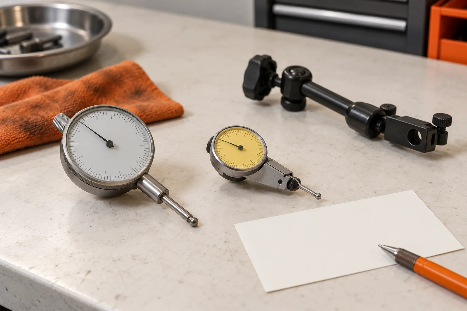
Identify the movement you are measuring
Dial indicator cosine error starts with geometry. An indicator can display a tidy value while its measuring direction is misaligned with the movement the technician intends to measure. Identify whether the instrument is a plunger indicator or a lever test indicator before adjusting its mounting.
Mitutoyo's Quick Guide explains that directional misalignment creates the cosine effect. A plunger's measuring movement follows its spindle. A lever test indicator measures in a direction perpendicular to the line from its stylus pivot to the contact point. The two arrangements therefore require different attention to alignment; a familiar dial face does not make their contact geometry interchangeable.
Preserve the setup before changing it
Before a repeat, save the original reading and describe the setup. Record the tool model, contact-point arrangement, feature location, mounting reference and intended movement. If practical, include a photo that shows the contact and mounting together. A close-up of the dial alone cannot document those relationships.
Mark missing setup evidence honestly. Do not retrospectively label the first reading “corrected” if the original alignment was never established.
For a vehicle-service decision, obtain the applicable procedure first. It determines the feature, mounting arrangement, instrument requirements and acceptance limit. This general guide does not authorize a new method or a substituted tool.
Minimize misalignment under the applicable instructions
Mitutoyo's guide advises minimizing the angle between movement directions and illustrates the lever stylus geometry separately. Use the exact instrument instructions and required measurement procedure to set the contact. Do not translate “make it square” into a universal instruction for every indicator.
This article intentionally gives no universal angle allowance or correction multiplier. The manufacturer's lever-indicator examples are tied to the geometry shown in its guide. Applying a remembered factor to a different tool, contact point or angle convention can create an unsupported result.
If the required arrangement cannot be achieved, record that limitation before making a service verdict. Obtain the appropriate tool or resolve the procedure question. A mathematical adjustment does not supply missing setup evidence.
Record a supported repeat as a new observation
Use the original setup record to explain what changed. A repeat should state the alignment adjustment, the instruction supporting it and the new reading in its original units. Keep both observations.
For example, an editorial handoff note could say: “First reading retained; contact arrangement was not documented. Repeated using the identified tool and applicable mounting instruction; see the new setup photo.” This is an invented documentation example, not a real measurement or proof that a particular component passed.
An alignment record for the next technician
The original downloadable card separates the indication from the supported service comparison:
- Tool ID, model and type: plunger indicator or lever test indicator.
- Contact point, mounting reference and applicable instructions.
- Vehicle, feature, location and intended movement.
- Original reading and units; setup photo or missing-evidence note.
- Repeat reason, changes and new observation.
- Applicable requirement, supported comparison and unresolved next check.
Use the brake runout versus thickness-variation guide when identifying which brake measurement answers the service question. It does not replace the vehicle procedure or this tool-alignment check.
Keep the handoff usable
A shop can use this card without any software: preserve what was observed, show how it was obtained and state what remains unresolved. That practical diagnostic handoff is relevant to STEP's mechanic audience. Request STEP Early Access to follow its development; no automated alignment or measurement capability is claimed here.
Sources and limits
The technical source is Mitutoyo's Quick Guide page 32. This is a source-based editorial explanation and an original record design. No instrument was tested, no angle was measured and no vehicle-specific tolerance is supplied.