
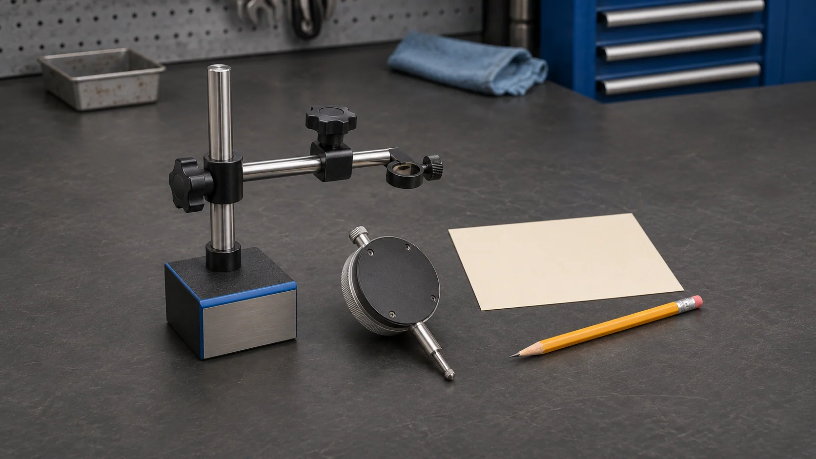
Separate part movement from setup movement
During a runout, endplay or other specified movement check, the displayed change is useful only with a defined reference and measurement arrangement. An unexplained change in the mounting can leave the component result uncertain. Do not immediately translate a wandering pointer into a worn part.
First preserve the original reading, units and setup. Record the indicator, base, arm arrangement, support surface, contact location and required component state. A photograph showing the whole mounting chain is more informative than a close-up of the dial alone.
Obtain the applicable vehicle procedure before choosing a mounting location or moving the component. It controls the required fixture, measurement direction, preparation and acceptance limit. This guide provides no substitute mounting point, vehicle tolerance or permission to work near moving machinery.
Inspect the reference-to-contact chain
Think through the chain from the supporting surface to the base, arm joints, indicator attachment and contact point. Identify which item is fixed and which item is intended to move. A magnetic switch in the on position is not, by itself, evidence that the complete arrangement is suitable.
The INSIZE MN-6216-E V1 instructions warn that contamination between that stand's base and its supporting surface can allow slight sliding that affects results. They also call for secure locking after adjustment and avoiding vibration. Apply the actual stand's instructions to its intended support surface; do not infer suitability from a magnet's advertised holding force.
Check the indicator attachment as well. Mitutoyo's Quick Guide, printed page 21, notes that excessive stem-clamping torque can impair spindle movement. Tightening harder is therefore not a universal solution. Use the specified mounting arrangement for the exact instrument, without borrowing another model's clamp dimensions or torque.
Contact alignment remains a separate question. See the dial indicator cosine-error guide for the distinction between plunger and lever instruments. A secure base does not correct the wrong contact geometry.
Keep the original zero and return observations
Before using the setup for a service decision, perform the operation and return checks required by the applicable instrument and measurement instructions. Mitutoyo specifically calls for checking operation and repeatability in certain indicator orientations; the product's specifications control the details.
Record the initial reference reading and each return reading in the displayed units. Do not rotate the bezel between observations merely to make the record look consistent. If re-zeroing is required after a setup change, preserve the earlier entry and label the new reference.
This article intentionally supplies no universal number of repeats or allowable number of dial divisions. An instrument specification, a setup check and a vehicle acceptance limit answer different questions. "It came back to zero" is an observation, not a complete calibration result.
Resolve an unstable setup before judging the part
If a return is inconsistent, stop the component disposition and identify what remains uncertain. Was the base displaced? Was a joint adjusted? Was the contact location changed? Record observed movement separately from a suspected cause. Do not claim that the base slipped unless that movement was established.
Where the applicable instructions permit a setup correction, document one change and repeat the relevant check. For example, keep a record of a cleaned support interface distinct from an indicator-remounting entry. Changing several items together may produce a better result while leaving the cause unresolved.
If the required arrangement cannot be secured or the instrument does not operate correctly, use the specified suitable equipment or obtain service guidance. Do not choose a different zero to obtain a preferred component verdict.
Make the setup repeatable for the next technician
Use the mounting and return-check record for:
- Instrument and stand identification, units and relevant instructions.
- Support surface, mounting chain, contact location and component state.
- Original reference and return readings, retained separately.
- Any observed setup movement, correction and new reference.
- Remaining limitations and the source supporting the final disposition.
The worksheet is an original recording aid. No stand was physically tested, and no calibration or vehicle inspection is certified by this article.
Clear handoffs also matter in electrical and network diagnosis. Request STEP access to discuss your shop's diagnostic workflow and availability. This guide does not claim STEP measures runout, calibrates indicators or approves mechanical service limits.