
Mechanic Guides
Multimeter Diode Test OL: Check the Test Limits Before Calling a Diode Open
Interpret OL in diode mode with polarity, meter range and circuit isolation recorded. Keep two-direction observations separate from a supported component verdict.
Published · 5 min read
Quick answer
OL in diode mode needs the meter range, lead polarity and component context. An open diode is one possible explanation; resolve the test capability and circuit paths before turning an OL/OL observation into a component verdict.
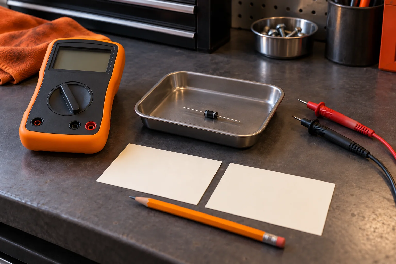
An OL indication in both diode-test directions can look decisive on a repair order. Before writing that a component is open, establish what was tested, how the leads were connected and whether the meter could make the required measurement. Two letters without that context leave the next technician with a conclusion that cannot be checked.
This guide concerns interpretation and documentation of a permitted diode test. Use the applicable vehicle, component and instrument instructions to establish de-energization, stored-energy precautions and isolation. Diode mode is not permission to probe an unidentified module or assembly.
Know what diode mode measures
The Fluke 88V Automotive Multimeter manual, printed page 22, describes applying a test current to a semiconductor junction and measuring its voltage drop. The displayed quantity belongs to that test condition. It is not a resistance measurement or a measurement of the component's normal operating supply voltage.
Select the specified function and document its symbol, units and input connections. A shared dial position can contain more than one function. The continuity-beep guide explains a different indication; its sound criteria should not be substituted for diode-mode instructions.
Read the instrument's overrange definition
An identified historical example makes the limitation concrete. The Fluke 8062A instruction manual, section 2-20 and Figure 2-14 on printed page 2-21, describes a 1 mA diode-test current and a 2 V display range, with OL above 2 V. Those values apply to that manual and model. They are not universal limits for shop multimeters.
A display can therefore report that the result is outside the function's measuring range. It does not supply the missing forward-voltage value. Check the actual meter's test capability against the identified component and its prescribed test conditions. If that comparison is unresolved, keep it unresolved in the record.
Do not apply a familiar silicon-junction expectation to every LED, multi-junction device or assembled component. Obtain the component identity and relevant procedure first. A different meter or test method is useful only when it is specified as suitable for the task; changing equipment just to obtain a preferred answer does not validate the answer.
Preserve both lead directions
Record one observation with the red lead on terminal A and black on terminal B, then the other with the lead positions reversed, where the procedure permits. Identify the terminals and any established anode/cathode reference. Do not infer polarity solely from which result looks familiar.
Keep a numeric observation with its units, or record OL exactly as shown. Preserve the meter mode and the original photograph or job-card entry. A note saying only “both ways bad” discards the evidence needed to distinguish an appropriate component test from an unsuitable setup.
Resolve other circuit paths
The 88V manual also explains that an in-circuit reverse-bias reading can depend on other paths between the probe tips. It calls for disconnecting circuit power and discharging capacitors before diode testing. Follow the exact applicable procedure for those actions rather than treating an ignition-off state as sufficient evidence.
Record whether the observation came from an isolated component or an in-circuit path, and what establishes that state. If the procedure requires isolation, perform only its permitted steps. An unexplained assembly connection is a reason to obtain the right test information, not to invent a removal or probing procedure.
Use a three-check handoff
Before an OL/OL observation becomes an open-diode verdict, resolve three questions:
- Is the component and its terminal identity established for this test?
- Is the meter function capable of the prescribed measurement, with the required setup verified?
- Is the isolation state appropriate, and does the result meet the applicable component test criteria?
Consider an invented handoff: “Diode mode selected; red A/black B gave OL; reversed leads gave OL. Component identity and the required test capability have not been established.” The useful next action is to obtain those missing facts and follow the permitted test. This example documents uncertainty; it does not describe a failed vehicle part.
The downloadable observation record keeps those checkpoints beside the original readings. Attach it to the diagnostic report template so another technician can see which conclusion is supported and which check remains. To discuss diagnostic handoffs in your independent shop, request STEP Early Access.