
Mechanic Guides
Thermocouple Cold Junction Compensation: Check the Probe Chain Before Trusting the Temperature
Check thermocouple reference compensation, input type and connections before comparing shop temperatures. Includes an original probe-chain handoff card.
Published · 5 min read
Quick answer
Cold junction compensation accounts for the reference-end temperature of a thermocouple measurement. Verify the configured probe type, compatible connections and the instrument reference conditions; do not add room temperature to an already compensated display.
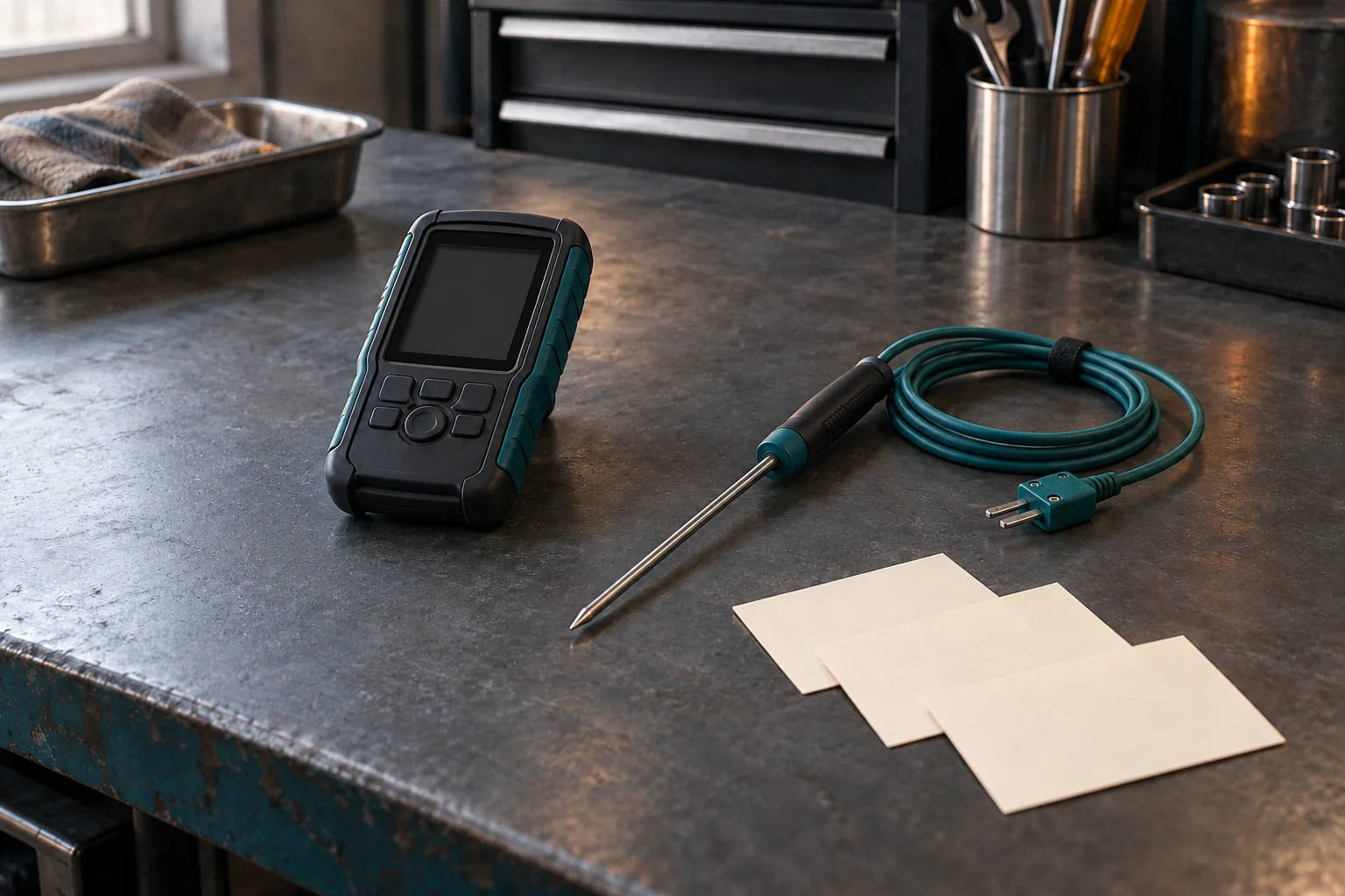
A contact temperature that changes unexpectedly can send a shop down the wrong diagnostic path. Before blaming the vehicle, identify how the thermocouple readout accounts for the temperature at its own input connection. The sensing tip is only one end of the measurement.
This guide covers an external shop thermocouple and its readout. It does not identify an installed vehicle sensor as a thermocouple, prescribe a vehicle temperature limit or replace the equipment's operating instructions.
What cold junction compensation actually does
A thermocouple uses two different metals. Its voltage depends on the temperatures at the measuring junction and the reference junction, rather than providing an absolute tip temperature by itself. Fluke's thermocouple fundamentals explains the reference connection and the electronic correction called cold junction compensation, or CJC.
The word cold does not require that connection to remain at ice temperature. A compatible readout can measure its reference temperature and account for it. That reference measurement belongs to the instrument's measurement chain; an unrelated ambient thermometer reading is not automatically a substitute.
CJC also does not turn the thermocouple into a calibrated, error-free assembly. Probe suitability, connections and the intended measurement still need to be established.
Checkpoint 1: identify the complete probe chain
Write down the readout model, input channel, selected thermocouple type and probe identity before interpreting a result. Match the actual probe to the configured input type. A temperature unit such as degrees Fahrenheit does not tell you whether the instrument is configured for the correct thermocouple.
Pico's thermocouple selection and use guide explains that probe type, insulation and construction affect the usable measurement range. It also specifies matching thermocouple extension wire, suitable connector materials and correct polarity. A connector that physically fits does not establish those facts.
Trace any extension or adapter between the tip and readout. Record its identity and compatibility evidence. If an unlabeled extension prevents that check, preserve the temperature observation but mark the measurement-chain question unresolved. Replacing the recorded number with a more plausible one does not resolve it.
Checkpoint 2: account for the reference end
The reference connection and its temperature sensor must represent the intended reference condition. Texas Instruments' A Basic Guide to Thermocouple Measurements, SBAA274A, section 1.3, explains the need for a known common temperature at the cold-junction connections. It also discusses thermal gradients and air currents.
For a shop check, document whether the readout and connector area have just moved between different environments, sit in a hot airflow or have otherwise changed condition. Follow the particular instrument's environmental and settling instructions before accepting a comparison. This article supplies no universal wait time.
Keep an exposed CJC or reference-temperature indication when the instrument provides one, together with its meaning from the manual. If it is not available, write that it was not exposed. Do not substitute the measured object's temperature for the reference-junction temperature.
Checkpoint 3: avoid correcting the display twice
Determine whether the saved value is a compensated temperature or an unconverted electrical measurement. A readout already reporting a compensated temperature needs no improvised addition of room temperature.
The TI guide, pages 7-8, explains that the thermocouple relationship is nonlinear: reference compensation is performed through the appropriate voltage-temperature relationship. Simply adding a reference temperature to a temperature inferred from the raw voltage is not the general conversion method. Use the supported readout or the documented calculation for the exact thermocouple type.
A stable-looking display is an observation. Record the applicable verification or calibration evidence separately; the display alone does not supply that evidence.
Use a probe-chain handoff card
Attach the original reading to a record that another technician can check:
- Measurement question, exact contact or sampling location, operating condition and time.
- Readout model and ID, channel, probe ID and selected thermocouple type.
- Extension and adapter identities, compatibility reference and polarity check.
- CJC mode or documented behavior; reference indication if available; recent environmental changes.
- Original displayed value and unit, saved electrical value if available, and any transformation applied.
- Applicable equipment verification evidence, comparison criterion and unresolved limitations.
The card keeps three outcomes separate: the chain is identified, a repeat is needed under documented conditions, or compatibility remains unresolved. None of those entries alone is a vehicle fault verdict.
In an invented handoff, a technician moves the readout from a cool cart into warm underhood airflow while monitoring a permitted external probe. The displayed temperature changes. The record retains both readings and the environmental change, then calls for a controlled repeat under the instrument instructions. This scenario does not prove either a CJC failure or a change at the vehicle measurement point.
For optical temperature measurements, use the separate infrared thermometer guide; thermocouple reference compensation does not address infrared emissivity. Attach the completed card to your diagnostic report. If your shop wants to discuss clearer measurement evidence and diagnostic handoffs, request STEP Early Access.