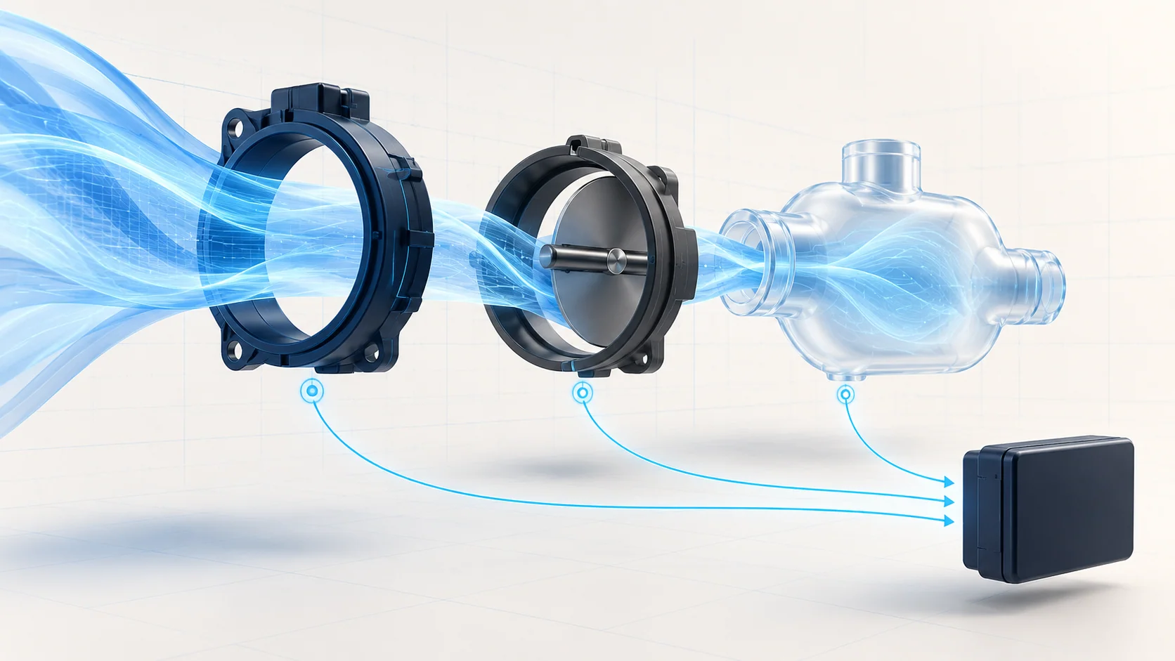
Airflow and load sensing helps the engine controller interpret how much air is entering the engine and whether the available measurements agree. On a Silverado 1500 5.3 gas engine, an airflow-related code is a starting point for separating an air-path problem from a signal, connection or plausibility concern. It is not an instruction to replace the sensor named by the code.
This educational introduction covers STEP's 2019–2025 Chevrolet Silverado 1500 5.3 Gas library. Early and late source configurations support that model-and-engine scope, not identical hardware, wiring or calibration across the range. The early source is the non-LD Silverado; do not substitute a Silverado LD procedure merely because its year and displacement match. Confirm the actual vehicle, engine variant and configuration before applying service information.
Purpose and operation
The mass airflow (MAF) input represents the mass of incoming air, not simply its volume. Manifold absolute pressure (MAP) describes pressure in the intake manifold. Throttle-position information provides another view of the engine's air demand and operating state. The controller can compare these inputs instead of accepting any one measurement as an independent truth.
The late-endpoint diagnostic description compares measured mass airflow with airflow calculated from throttle position and from manifold pressure. A disagreement can therefore arise from incorrect information or from an actual condition that changes airflow. A correlation code does not tell the technician which input is wrong.
Intake-air temperature information adds context to intake-air diagnosis. The early-endpoint source describes a multifunction intake-air sensing assembly, while the late source uses different component designations. This overview does not claim identical packaging, sensor count, communication method or connector layout throughout the catalog range. Confirm what the installed assembly measures before interpreting shared faults.
How the linked guides fit
P0068 Diagnostic Guide introduces throttle-body airflow performance and disagreement among the airflow calculations. It is a comparison problem, not proof that the throttle body needs replacement.
P0101 — Mass Air Flow Sensor Performance addresses measured airflow that does not agree with the controller's expectation. Investigate the air path and the other inputs as well as the MAF information.
P0102 Diagnostic Guide belongs to a different category. The early-endpoint definition concerns a low-frequency MAF circuit signal. A low signal is not automatically proof that actual engine airflow is low or that the sensing element has failed.
P0113 Diagnostic Guide adds intake-temperature circuit context. The early-endpoint definition is an intake-air temperature sensor circuit-high concern. Do not translate that electrical label into a conclusion that the incoming air is physically too hot. Use the complete code, subtype and applicable diagnostic definition.
These links organize the investigation. Exact test values, terminals, monitor conditions and procedures remain limited to the source target that proves them; they are not range-wide specifications.
Failure categories and symptoms
Air-path integrity is one category: loose or damaged ducting, leaks, restrictions and disturbed installation can change the relationship among measured airflow, manifold pressure and throttle position. Intake or exhaust restrictions, PCV concerns and engine mechanical conditions may also affect that relationship. A performance code can reflect a real airflow problem even when a sensor is reporting what it sees.
Measurement and electrical integrity are separate categories. Contamination, water intrusion or physical sensor damage can matter. So can a poor connection, damaged terminal, interrupted supply or ground, or the applicable signal or data circuit. Several related values becoming implausible together is useful context, but it does not identify a shared failed part without tests.
The truck may have an illuminated malfunction indicator lamp, rough idle, hesitation, reduced response or a power complaint. It may also have few obvious symptoms. Those complaints have other causes; neither the symptom nor the code pattern substitutes for diagnosis.
A practical diagnostic strategy
Preserve the complete code list and available failure data before clearing anything. Record the operating state and recent work, especially disturbed intake parts or connectors. Review related supply, reference, throttle, pressure and communication concerns before narrowing the case to one airflow code.
Inspect accessible air-path components and connections with the engine safely stopped. Look for actual damage, poor seating, contamination or an installation problem. Do not use an inspection result to claim that an electrical circuit is sound, or a plausible scan value to certify that the entire intake is leak-free.
Compare scan information under the applicable conditions. Pressure interpretation depends on operating state and atmospheric context; a generic idle value is not a universal standard. Review changes and intermittent dropouts rather than relying only on one snapshot. Correlated changes help select the next test, not skip it.
Use the prescribed leak-test method and equipment when the diagnostic path calls for it. Do not invent a pressure setting or substitute an unsafe spray test. Electrical checks require the correct circuit identification, reference point, meter mode, isolation and adapters. Do not apply battery voltage to a sensor signal circuit or copy a jumper test from another configuration.
Repair and verification
Repair the demonstrated fault: an air-path defect, connection, wiring, installation issue or a component supported by the applicable tests. Cleaning is appropriate only when the component's service procedure permits it. Do not touch a delicate sensing element or assume that a general solvent is compatible. Throttle cleaning, adjustment and relearning are not universal first steps.
After repair, restore intake joints, connectors and routing correctly. Perform only the specified reset, learning and verification actions for that configuration. Recheck the original complaint, relevant data and codes under safe conditions that exercise the original concern. Clearing the lamp or completing one normal idle period does not prove that an intermittent fault is resolved.
Safety and scope
Secure the vehicle, provide exhaust ventilation and keep tools and leads clear of fans, belts and other moving parts. Prevent unintended operation before disconnecting components, and follow the required power-down procedure. Let hot intake-adjacent and exhaust components cool before access.
Use approved support if underbody access is required. Keep away from an electronically controlled throttle mechanism during commanded operation. Stop if a required test cannot be identified or performed safely; the purpose of this overview is to organize evidence, not replace the vehicle-specific service procedure.