What this code means
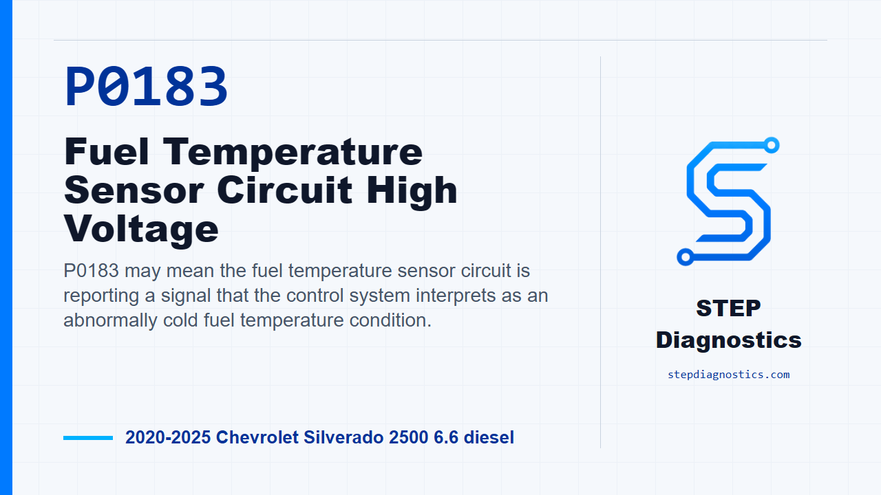
P0183 may mean the fuel temperature sensor signal circuit is being interpreted as higher voltage than expected, often showing an unusually cold fuel temperature reading.
What the vehicle may do
- The vehicle may turn on the check engine light.
- The engine may run normally, or it can have possible fuel system or drivability symptoms depending on the fault.
- The code may return if the circuit condition is still present when the monitor runs.
Possible fault areas
- Possible fuel temperature sensor or sensor assembly concern.
- Possible signal circuit concern.
- Possible low reference or ground concern.
- Possible connector, harness, or control module circuit concern.
Diagnostic path
Opening context
On this Silverado diesel, P0183 is a fuel temperature sensor circuit high voltage code. In plain language, the module may be seeing a fuel temperature signal that looks colder than expected for the circuit. The truck may have a check engine light, and depending on the fault, it can have fuel system or drivability symptoms, but this diagnosis is mainly about proving the sensor signal, low reference, ground, wiring, and the fuel pump driver control module path before calling a part bad.
Start with the basic checks
Before getting into the pinpoint tests, start with the basic system checks. If other codes are present, check what they mean first, then follow a structured diagnostic approach so you are not chasing a circuit fault with a broader vehicle problem still active.
Use the scan value as your first clue
Use the fuel temperature scan value to decide which direction the circuit is pointing. The normal parameter range is −39 to 109°C (−38 to 228°F). In the typical scan data, a signal short to ground is shown as Signal 110°C (230°F), a signal open is shown as Signal −40°C (−40°F), a signal short to voltage is also shown as Signal −40°C (−40°F), and a low reference open is shown as Low Reference — −40°C (−40°F) —. That is why this P0183 path pays close attention to a cold-looking scan value and then proves the wiring before blaming a component.
Understand when P0183 runs and sets
For P0183, treat the running conditions as monitor gates. The fuel pump driver control module voltage signal has to be greater than 8 V, ignition is on or the engine is running, ignition voltage has to be greater than 11 V, and the monitor runs continuously after those conditions are met. The setting condition for P0183 is the fuel temperature sensor reading colder than -39°C (-38°F) for greater than 2 s.
Initial scan tool verification
With ignition on and the vehicle in Service Mode, look at the Fuel Temperature Sensor parameter. It should be between −39 and 109°C (−38 and 228°F), and it should change. If it is in that range and changes, reproduce the operating conditions, or reproduce the captured conditions, and verify P0183 does not reset. If the code does not reset, that path checks good. If the parameter is out of range, does not change, or the code resets during the check, move into circuit testing.
Power down and check the low reference first
For circuit testing, turn the ignition and all vehicle systems off, then disconnect the E11A Fuel Heater/Water in Fuel Sensor connector. Remember, it may take up to 2 min for all vehicle systems to power down before a ground or low reference continuity test is accurate. Test the low reference circuit at terminal 7 to ground. You want less than 10 Ω.
If low reference resistance is high
If terminal 7 to ground is 10 Ω or greater, disconnect the K111 Fuel Pump Driver Control Module connector and isolate the low reference circuit. Test from low reference terminal 7 at the component harness to terminal 19 at the control module harness. The circuit should be less than 2 Ω. If it is 2 Ω or greater, repair the open or high resistance in that circuit.
If the low reference wire is good, check module ground
If that low reference circuit is less than 2 Ω, move to the control module ground side. Test ground circuit terminal 14 at the control module harness to ground. It should be less than 10 Ω. If it is 10 Ω or greater, disconnect ground G415 and test ground circuit terminal 14 to terminal G415. That should be less than 2 Ω. If it is 2 Ω or greater, repair the open or high resistance in the circuit. If that section is less than 2 Ω, repair the open or high resistance in the ground connection. If terminal 14 to ground was already less than 10 Ω on this branch, the procedure calls for replacing the K111 Fuel Pump Driver Control Module.
If low reference is good, check the sensor signal response
If the low reference circuit terminal 7 to ground is less than 10 Ω, turn ignition on with the vehicle in Service Mode. Now verify the scan tool Fuel Temperature Sensor reads colder than −39°C (−38°F). If it reads warmer than −40°C (−40°F), turn ignition off, disconnect the K111 Fuel Pump Driver Control Module, and test signal circuit terminal 6 at the component harness to ground for infinite resistance. If you have less than infinite resistance, repair the short to ground on the signal circuit. If resistance is infinite, the procedure calls for replacing the K111 Fuel Pump Driver Control Module.
Use a fused jumper to prove the signal and low reference together
If the scan tool does read colder than −39°C (−38°F), connect a 3 A fused jumper wire between signal circuit terminal 6 and low reference circuit terminal 7. With that jumper in place, the Fuel Temperature Sensor parameter should go warmer than 109°C (228°F). This is the sensor simulation part of the test: you are proving whether the module can see the circuit move when the signal and low reference are tied together through a protected jumper.
If the jumper does not drive the scan value warm
If the scan value stays 109°C (228°F) or colder with the jumper connected, turn ignition off, remove the jumper, disconnect the K111 Fuel Pump Driver Control Module, then turn ignition on with the vehicle in Service Mode. Test signal circuit terminal 6 at the component harness to ground. You want less than 1 V. If it is 1 V or greater, repair the short to voltage on the signal circuit.
If voltage is low, check signal circuit continuity
If signal circuit terminal 6 to ground is less than 1 V, turn ignition off and test continuity from signal circuit terminal 6 at the component harness to terminal 4 at the control module harness. The circuit should be less than 2 Ω. If it is 2 Ω or greater, repair the open or high resistance in the signal circuit. If it is less than 2 Ω, the procedure calls for replacing the K111 Fuel Pump Driver Control Module.
If the jumper response is correct
If the fused jumper makes the Fuel Temperature Sensor parameter read warmer than 109°C (228°F), the circuit response is correct on that branch. At that point, the procedure calls for replacing the E11A Fuel Heater/Water in Fuel Sensor.
Verify the repair
After the repair is complete, keep verification separate from the circuit testing. Verify the repair and confirm P0183 stays gone under the operating conditions that run the monitor.
Closing takeaway
The key with P0183 is to prove the low reference, ground, and signal circuit response before condemning the sensor or the module. Work the branches in order, protect the jumper test, and let the scan data confirm the direction. For more diagnostic training, visit stepdiagnostics.com.
Final check
P0183 is best handled as a circuit diagnosis: confirm the scan value, simulate the sensor response, then repair only the branch that fails testing.
For more guided automotive diagnostics, visit STEP Diagnostics.