What this code means
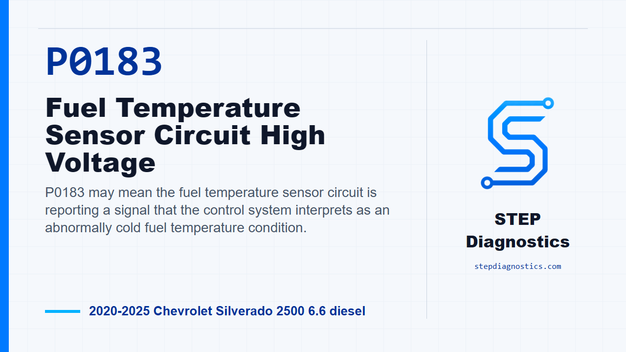
P0183 may mean the fuel temperature sensor circuit is reporting a signal that the control system interprets as an abnormally cold fuel temperature condition.
What the vehicle may do
- The vehicle may run normally with a warning light.
- Fuel system control behavior may be affected depending on related faults and operating conditions.
- The code may return when the monitor runs if the circuit condition is still present.
Possible fault areas
- Possible fuel temperature sensor issue within the fuel heater and water-in-fuel sensor assembly.
- Possible signal circuit fault.
- Possible low reference or ground integrity issue.
- Possible fuel pump driver control module involvement.
Diagnostic path
Opening and code context
On this 2020 to 2025 Chevrolet Silverado 2500 with the 6.6 diesel, P0183 is a fuel temperature sensor circuit high voltage code. In plain terms, the module is seeing the fuel temperature signal in a range that can look colder than it should. The truck may run normally, or it may have a warning light and fuel system behavior may be affected depending on what else is going on. Broadly, this can point toward the fuel temperature sensor inside the fuel heater and water-in-fuel sensor assembly, the signal circuit, the low reference, ground integrity, or possible fuel pump driver control module involvement. Start with the basic system checks, and if other codes are present, understand their meaning before chasing this one. Then follow a structured diagnostic approach instead of jumping straight to a part.
System and monitor logic
The fuel temperature sensor is a negative temperature coefficient thermistor. As temperature increases, sensor resistance decreases, and that changes the voltage on the signal circuit. The sensor is integrated into the E11A fuel heater and water-in-fuel sensor. The K111 fuel pump driver control module is also part of this diagnostic path. For P0183, think of the run conditions as monitor gates: the related enabling codes must not be active, the fuel pump driver control module voltage signal must be greater than 8 V, ignition must be on or the engine running, and ignition voltage must be greater than 11 V. The code sets when the fuel temperature sensor reads colder than -39°C (-38°F) for greater than 2 s. Typical scan data gives you some direction here: a signal short to ground is shown as 110°C (230°F), a signal open is shown as −40°C (−40°F), a signal short to voltage is also shown as −40°C (−40°F), and an open low reference is shown as −40°C (−40°F).
Circuit and system verification
Begin verification with the ignition on and the vehicle in service mode. Watch the scan tool fuel temperature sensor parameter. It should be between −39 and 109°C (−38 and 228°F), and it should change. If it is outside that range, or it does not change, go into circuit testing. If the parameter is in range and changes, reproduce the operating conditions for the monitor. You can also reproduce the captured conditions from the stored data. Then confirm P0183 does not reset. If it resets, move into circuit testing. If it does not reset, the system checks out at this point.
Start circuit testing at the low reference
For circuit testing, power the ignition and all vehicle systems off. Give the vehicle enough time to shut down; it may take up to 2 min before a ground or low reference continuity test is accurate. Disconnect the E11A fuel heater and water-in-fuel sensor connector. First test between low reference circuit terminal 7 and ground. You want less than 10 Ω. If that test is 10 Ω or greater, disconnect the K111 fuel pump driver control module connector and check the low reference circuit from terminal 7 at the component harness to terminal 24 at the control module harness. That should be less than 2 Ω. If it is 2 Ω or greater, repair the open or high resistance in that circuit.
Check control module ground path if low reference continuity is good
If the low reference circuit is less than 2 Ω, stay on the K111 side and test from ground circuit terminal 14 at the control module harness to ground. That test should be less than 10 Ω. If it is 10 Ω or greater, disconnect ground connection G415 and test from ground circuit terminal 14 to terminal G415. That should be less than 2 Ω. If that circuit is 2 Ω or greater, repair the open or high resistance in the circuit. If it is less than 2 Ω, repair the open or high resistance in the ground connection. If the ground circuit terminal 14 to ground test was already less than 10 Ω, the diagnostic path calls for replacing the K111 fuel pump driver control module.
Check for the expected cold reading with the sensor disconnected
If the original low reference terminal 7 to ground test was less than 10 Ω, turn the ignition on with the vehicle in service mode. With the E11A disconnected, verify the scan tool fuel temperature sensor parameter is colder than −39°C (−38°F). If the scan tool shows warmer than −40°C (−40°F), turn the ignition and vehicle off, disconnect the K111 fuel pump driver control module connector, and test the signal circuit terminal 6 at the component harness to ground. That resistance should be infinite. If it is less than infinite resistance, repair the short to ground on the signal circuit. If it is infinite resistance, the diagnostic path calls for replacing the K111 fuel pump driver control module.
Simulate the sensor response with a fused jumper
If the scan tool does show colder than −39°C (−38°F), connect a 3 A fused jumper wire between signal circuit terminal 6 and low reference circuit terminal 7. Now the scan tool fuel temperature sensor parameter should read warmer than 109°C (228°F). If it is 109°C (228°F) or colder, turn the ignition and vehicle off, remove the jumper wire, disconnect the K111 connector, turn the ignition back on with the vehicle in service mode, and test signal circuit terminal 6 at the component harness to ground. You should see less than 1 V. If you see 1 V or greater, repair the short to voltage on the signal circuit.
Finish signal circuit continuity and sensor decision
If the signal circuit voltage test is less than 1 V, turn the ignition and vehicle off and check continuity on the signal circuit from terminal 6 at the component harness to terminal 36 at the control module harness. That should be less than 2 Ω. If it is 2 Ω or greater, repair the open or high resistance in the signal circuit. If it is less than 2 Ω, the diagnostic path calls for replacing the K111 fuel pump driver control module. Back at the jumper test, if the fuel temperature sensor parameter went warmer than 109°C (228°F), the circuit response is correct and the diagnostic path calls for replacing the E11A fuel heater and water-in-fuel sensor.
Repair verification and takeaway
After the repair, keep verification separate from the circuit testing. Verify the repair and confirm the code stays gone under the proper operating conditions. The clean way through P0183 is to prove the low reference first, then prove the module ground, then simulate the signal circuit and let the scan tool response tell you whether the fault is in the wiring, the module, or the sensor assembly. For more diagnostic training, visit stepdiagnostics.com.
Final check
Use scan tool response and circuit checks to separate a wiring fault from a sensor assembly or module fault.
For more guided automotive diagnostics, visit STEP Diagnostics.