What this code means
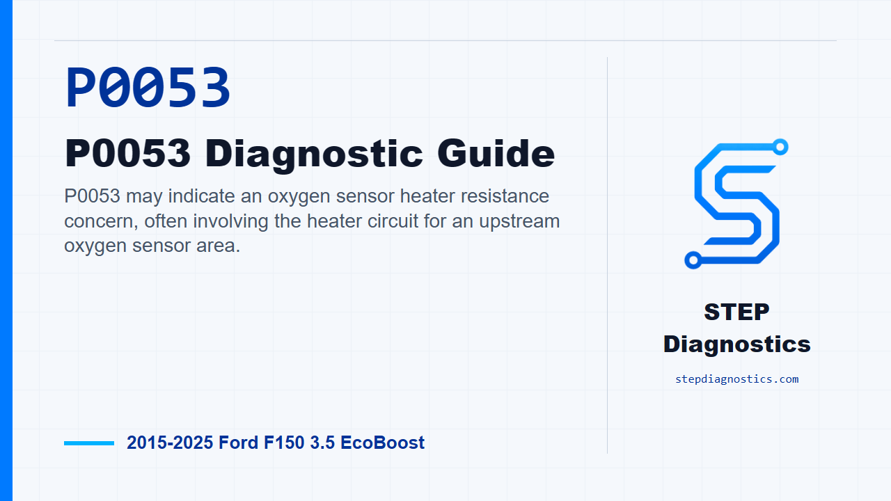
P0053 may indicate an oxygen sensor heater resistance concern, often involving the heater circuit for an upstream oxygen sensor area.
What the vehicle may do
- The vehicle may turn on the check engine light.
- The vehicle may seem to drive normally even with the code stored.
- Emissions monitor readiness or fuel-control related monitoring may be affected.
Possible fault areas
- Possible oxygen sensor heater circuit concern.
- Possible connector or terminal issue.
- Possible wiring, power, ground, or control-side circuit issue.
- Possible damage near the exhaust area where heat and routing can affect wiring.
Diagnostic path
Open on what P0053 means and set the boundary
On this F-150 with the 3.5 EcoBoost, P0053 may point to an oxygen sensor heater resistance concern. The truck may drive normally, or it may turn on the check engine light and affect emissions monitor operation. Broadly, you’re thinking about a possible heater-side sensor issue, connector or terminal trouble, wiring damage, power, ground, or the control side of the circuit. For this episode, the path is a routing and basic electrical-check approach. There is not a P0053-specific pinpoint test, monitor condition list, connector callout, or confirmed repair here, so do not jump straight to a part.
Confirm the concern before testing
Start by confirming the concern is actually present. That matters because you do not want to condemn a module or another component when the concern is not there during testing. Before you get deep into the code, do the basic preliminary checks: look for any obvious issue tied to the customer complaint, check for applicable Ford messages or bulletins, and look at any previous repairs that could have been done incorrectly.
Stabilize the vehicle before diagnosis
Next, make sure the electrical foundation is solid. Check the battery and charging system for correct operation, and verify the battery SOC is greater than 70% before beginning diagnostics. On a heater-circuit type concern, weak system voltage or an unstable charging system can send you down the wrong road, so get that handled before chasing the circuit.
Use the codes to choose the starting point
Now scan all network modules for related system or symptom codes. If other codes are present, check what they mean first and use them to decide where to start. Circuit-related codes take priority over system or performance-type codes. If you have multiple circuit faults, slow down and look for a common power or ground issue, like a shared splice, instead of treating every code like a separate failure.
Do the physical and connection basics first
Before any detailed electrical testing, inspect the harnesses for damage, chafing, and correct routing. Check fuses, circuits, and connectors for continuity and correct installation, and make sure the components are properly connected. These are simple checks, but on an oxygen sensor heater type concern, damaged routing or a poor connection can look like a deeper circuit failure.
Finish the supporting vehicle checks in order
Keep going through the basic vehicle checks before narrowing the diagnosis. Inspect the vacuum lines and air intake system for leaks, routing problems, or restrictions. Inspect hoses for damage, leaks, blockage, and correct routing. Check fuel quality, including octane, contamination, and winter or summer blend. Inspect the fuel system, including the fuel tank and fuel lines, for damage, leaks, and correct routing. Check coolant level and quality with the engine at the correct operating temperature. Check oil level and quality, including contamination and correct maintenance. Then inspect the exhaust system for damage, restrictions, and correct routing, especially because this concern can involve wiring and connectors near the exhaust.
Pick the right circuit load
When the diagnosis turns into electrical testing, match the load to the circuit. Circuits carrying approximately 200-1000 mA may be loaded with a 250-350 mA test light. Conductor sizes 24 gauge (0.5 mm) or smaller are generally used to carry approximately 1000 mA (1 ampere) or less, and use of a 250-350 mA test light to load these circuits is appropriate. Circuits carrying more than one ampere should be loaded with a device requiring similar current, for example a brake light bulb. Conductor sizes 20 gauge (0.8 mm) or larger are generally used to carry 1 ampere (1000 mA) or more.
Use resistance checks with the right expectations
For resistance checks, keep the numbers in perspective. Expect less than 2 ohms for most small diameter, 18 gauge and smaller wires. For most wiring harness circuits, expect less than 2 ohms of resistance. A standard DMM ohmmeter’s low-resistance resolution, approximately 0.1 ohm, limits its accurate use to circuits carrying less than approximately 5 amperes. When checking a suspect circuit to ground, disconnect both ends of the circuit, measure between the suspect circuit and ground, and expect resistance greater than 10,000 ohms. When checking between two unpowered circuits, disconnect both ends of the two circuits, measure between the two circuits with an ohmmeter, and expect resistance greater than 10,000 ohms.
Use voltage-drop numbers as the decision point
Voltage-drop testing should show only a small amount of normal circuit loss, so expect less than 5 percent of circuit operating voltage. In 12-volt circuits, that normal loss is usually less than 0.5 volts, again expecting less than 5 percent of circuit operating voltage. Voltage indications greater than 0.5 volts indicate abnormal voltage loss. With a voltage-in, voltage-out style check, the power side should be within 0.5 Volts of battery voltage, and the ground side should be greater than 0 volts but less than 0.5 volts.
Protect the terminals and the module-controlled circuits
Use the proper terminal probes and do not force test leads into connectors. Back-probing is only for a circuit that has to be checked under actual operating conditions, and it is the wrong approach for a single-point voltage check where zero volts is possible, or for checking continuity and opens with an ohmmeter. In those cases, disconnect and isolate the circuit, then test it normally. Also, do not apply power or ground directly to module-switched components unless the diagnostic path specifically tells you to. If jumper wires are used, always use fused jumper wires; the recommended universal-testing jumper wire fuse is 5 amperes or less, with larger fuse ratings used only when the load requires them. Flex probes are not intended to carry high current greater than 5 amperes, so do not use them to power high-current devices.
Do not hide the root cause
If you find a wiring problem, do not cover it up by adding a parallel wire without understanding why the circuit failed. Find the fault, inspect the affected wiring, and correct the root cause so you are not leaving damaged adjacent wiring behind.
Verification boundary and takeaway
Keep the testing phase separate from verification. Because this path does not provide the P0053-specific monitor gates or pinpoint branches, avoid guessing at a missing return point. After correcting an obvious or confirmed fault, pause, recheck the earlier diagnostic path, and make sure the original concern is no longer present before calling it done. The takeaway: qualify the complaint, stabilize the electrical system, prioritize circuit faults, inspect the vehicle basics, then test the wiring and connectors carefully without damaging the terminals. For more diagnostic training, visit stepdiagnostics.com.
Final check
P0053 should be approached as an electrical diagnostic: confirm the concern, check the vehicle’s electrical foundation, prioritize circuit faults, and inspect the wiring and connectors before making a
For more guided automotive diagnostics, visit STEP Diagnostics.