What the fuel system does
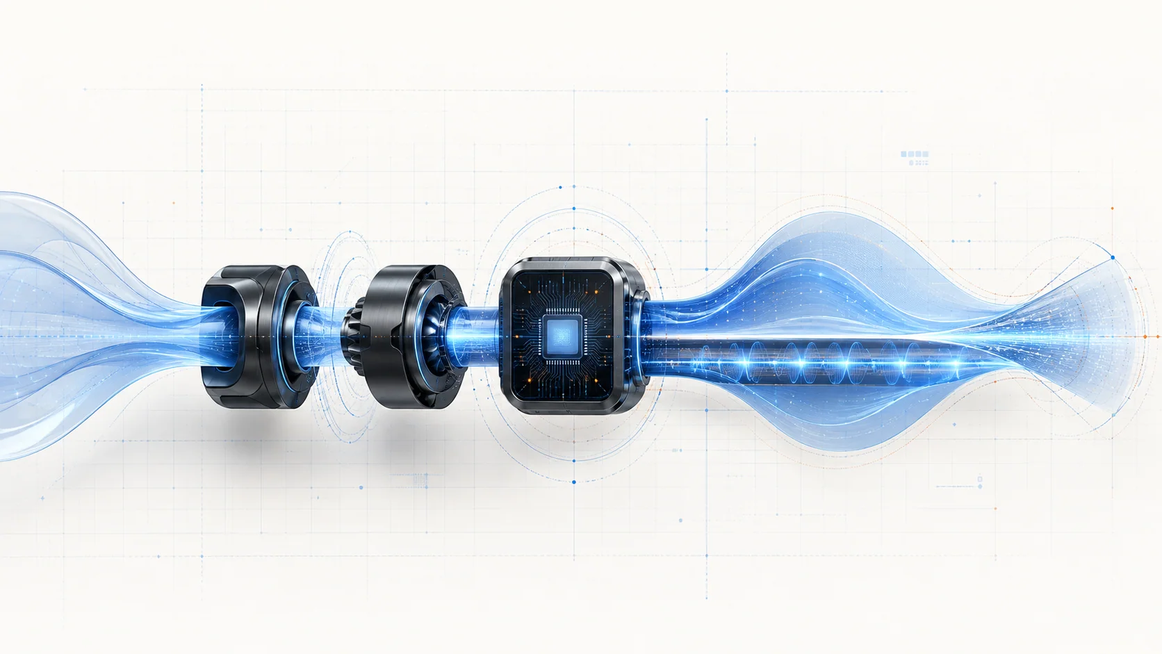
The 3.5-liter EcoBoost fuel system must move gasoline from the tank, provide stable supply to the engine, generate the pressure needed for direct injection, meter fuel cylinder by cylinder, and continually correct delivery as operating conditions change. The powertrain control module (PCM) coordinates pump control, fuel-pressure and temperature information, injector operation, airflow inputs, and exhaust feedback.
Ford model-year material confirms that the F-150 was offered with a 3.5L EcoBoost engine throughout the 2015-2025 range. The detailed operating and diagnostic information reviewed for this overview comes from the exact 2025 F-150 4WD 3.5L turbo application. Verify the VIN, engine calibration, actual injection layout, connector information, specifications, and current service procedure for the truck being repaired. Exact hardware and procedures can differ within the grouped range.
A fuel-system DTC reports a behavior the PCM could not verify. It does not automatically prove that a pump, sensor, injector, or PCM has failed. P0087, P0183, and P0201 belong to the same broad system but point to different diagnostic categories: pressure performance, a sensor circuit, and an individual injector circuit.
The main functional sections
- Low-pressure supply: The in-tank pump and supply path deliver fuel toward the engine. The low-pressure side must supply the high-pressure stage consistently, so one pressure result cannot prove that both stages work correctly.
- High-pressure generation and control: An engine-driven high-pressure pump raises fuel pressure for direct injection. The PCM regulates delivery through the pump's fuel-volume control while monitoring whether actual pressure follows the requested condition.
- Rails and pressure feedback: Fuel rails distribute fuel to the injectors. Pressure sensors provide feedback that the PCM uses for control and fault detection.
- Fuel-pressure and temperature sensing: The low-side pressure/temperature sensor supplies information used for pump control and diagnostic decisions. A temperature-circuit DTC concerns signal integrity first; it is not proof that the fuel itself is abnormally hot.
- Direct and port injection: The exact late-range application reviewed here uses both direct and port fuel injection. The PCM can coordinate their contribution according to operating strategy. Confirm the system fitted to the specific model year before testing or parts decisions.
- Airflow and exhaust feedback: Airflow, pressure, temperature, oxygen-sensor response, and learned fuel trims help the PCM judge whether commanded delivery produced the expected mixture.
How supply, pressure, injection, and feedback work together
The low-pressure pump feeds the engine-driven high-pressure pump. The high-pressure stage supplies the direct-injection rail, while the applicable port-injection circuit has its own delivery path. The PCM calculates the fuel required for current speed, load, temperature, and driver demand. It then commands pump control and injector timing and duration while comparing sensor feedback with the intended result.
This is a connected control loop. A restricted supply can prevent the high-pressure stage from meeting demand. A biased pressure signal can make a mechanically sound system appear incorrect. An injector circuit fault can affect one cylinder even when overall rail pressure looks reasonable. Air-measurement, purge, ignition, compression, or exhaust-feedback problems can also change fuel trims and drivability without a primary fuel-hardware failure.
That interaction is why diagnosis should begin with the type of failed behavior, not with the most expensive component named near the code description.
What the related DTCs are telling you
| DTC | Diagnostic category | What it directs you to prove |
|---|---|---|
| P0087 | Fuel rail/system pressure too low | Whether low-side supply, high-pressure generation, volume control, feedback, leakage, electrical control, or operating conditions explain why pressure did not meet the requested result |
| P0183 | Fuel-temperature signal circuit high | Whether the pressure/temperature sensor signal, reference/return path, connector, wiring, or sensor explains the electrically high indication |
| P0201 | Cylinder 1 injector circuit | Whether the injector, wiring, terminal fit, or PCM driver prevents the circuit from responding correctly |
P0087 is not a high-pressure-pump replacement instruction. P0183 is not proof of excessive fuel temperature. P0201 is not proof that cylinder 1's injector is clogged. Each code narrows the evidence needed, but the directed diagnosis must still identify the cause.
What the driver or technician may notice
Possible observations include:
- a malfunction indicator lamp with few immediate symptoms;
- long crank, difficult starting, hesitation, reduced power, or stalling when pressure supply is inadequate;
- rough running or a cylinder-specific misfire sensation during an injector-circuit fault;
- a fault that appears only under load, after a hot soak, or when a connector or harness moves;
- pressure data that cannot follow command during the condition recorded in freeze-frame data;
- implausible fuel-temperature data compared with ambient and other temperature inputs;
- companion fuel-pump, pressure-sensor, injector, misfire, airflow, voltage, or communication codes.
Symptoms help reproduce the concern but do not identify the failed part. Similar drivability complaints can come from air, ignition, exhaust, mechanical, electrical, or fuel-quality faults.
Safety before testing
Gasoline and fuel vapor are flammable. Both the low-pressure and direct-injection sides can retain pressure after the engine is switched off. Work in a ventilated area away from sparks, flame, hot surfaces, and unapproved electrical equipment. Wear eye protection, contain released fuel, and use the exact pressure-relief procedure before opening any line, rail, pump, sensor, or injector connection.
Allow hot turbocharger and exhaust-area parts to cool before reaching into the fuel system or harness. Support the vehicle correctly if access underneath is required. Inspect for external leakage before running the engine and stop testing if a leak is found.
Direct-injection injectors and pump-control components can be damaged by improvised power application. Do not apply battery voltage directly to an injector or fuel-volume-control terminal. Use terminal-safe probes, the correct wiring information, and the directed test for the exact truck.
Common failure categories
1. Low-pressure supply or fuel-quality problem
A weak in-tank pump, restricted pickup or filter, damaged line, electrical supply problem, contamination, incorrect fuel, or external leakage can starve the high-pressure stage. Verify the low side under the condition that produced the fault before condemning the engine-driven pump.
2. High-pressure generation or control problem
The high-pressure pump, its mechanical drive, fuel-volume control, rail, pressure-feedback path, or internal leakage can keep actual pressure from following command. Requested-versus-actual behavior is useful only when the correct PID, operating condition, and service specification are used.
3. Pressure or temperature sensor circuit problem
An open circuit, short, corrosion, poor terminal fit, damaged reference or return path, harness movement, or failed sensor can create an implausible signal. P0183 begins as a circuit diagnosis; interpret the displayed temperature as a real physical condition only after signal integrity is established.
4. Individual injector circuit problem
P0201 concerns the cylinder 1 injector circuit. Wiring damage, connector trouble, an electrically faulty injector, or a PCM driver concern can prevent correct operation. Keep electrical response separate from injector flow and mechanical cylinder condition.
5. Injector flow, leakage, or deposit concern
An injector can have a mechanical flow problem without producing the same evidence as an electrical circuit DTC. Use the applicable balance, contribution, leakdown, or directed injector test after pressure and circuit evidence justify that branch.
6. Non-fuel fault influencing fuel evidence
Incorrect airflow information, unmetered air, purge flow, biased oxygen feedback, weak ignition, low compression, valve-timing trouble, or low system voltage can imitate or worsen a fuel-system complaint. Companion codes and cross-system data prevent a fuel-only diagnosis when the cause lies elsewhere.
A practical diagnostic sequence
1. Preserve the evidence
Scan all modules before clearing codes. Save freeze-frame or snapshot data, DTC status, requested and actual pressure data, fuel-temperature information, fuel trims, misfire counters, system voltage, and the load and temperature at which the fault set. Record recent fuel, wiring, engine, calibration, or collision work.
2. Establish code priority
Address low voltage, lost communication, reference-voltage, shared-power, and direct circuit faults before trusting performance data influenced by those circuits. Use the current service-information priority when multiple codes are present.
3. Perform safety and visual checks
Check for fuel leakage, damaged or incorrectly routed lines, loose intake plumbing, disturbed connectors, heat or abrasion damage, contamination, and poor terminal fit. A visual inspection should guide tests, not replace them.
4. Separate the low- and high-pressure stages
For P0087, first decide whether the high-pressure pump is receiving adequate low-side supply. Then compare requested and actual high-pressure behavior using the exact procedure. A correct low-side result does not prove the high side, and low rail pressure does not identify the failed component by itself.
5. Treat circuit codes as circuit evidence
For P0183, compare the fuel-temperature input with other temperature information and test the signal, reference, return, connector, and harness as directed. For P0201, confirm the individual circuit, injector electrical behavior, and driver control before replacing a component.
6. Reproduce the recorded condition
An idle-only check may miss a pressure fault that occurs under load. A cold inspection may miss a heat-sensitive terminal. Reproduce the freeze-frame condition safely while watching the smallest set of relevant data.
7. Confirm the cause before repair
Use the applicable pressure, volume, circuit-load, injector, fuel-quality, air, ignition, or mechanical test only after the preceding evidence supports that branch. Do not substitute a generic specification or another model year's connector view for the current procedure.
8. Verify the repair
After correcting the proven cause, inspect for leakage, clear codes or learned values only when instructed, repeat the applicable self-test or drive condition, and confirm that pressure control, temperature data, injector operation, and drivability are stable. Re-scan all modules and make sure no new fault was introduced.
Repair direction by confirmed cause
- Repair leakage, contamination, damaged lines, or low-pressure supply faults before evaluating high-pressure components.
- Repair power, ground, reference, return, signal, connector, terminal, or harness faults before replacing a sensor or injector.
- Replace a pressure/temperature sensor only when its circuit and response fail the directed test.
- Replace an injector only when electrical or flow evidence identifies it and the related circuit has been proven.
- Service the high-pressure pump or control hardware only after supply, mechanical drive, control, feedback, and requested-versus-actual evidence support that decision.
- Diagnose airflow, purge, ignition, exhaust-feedback, compression, or timing faults when they explain the observed fuel evidence.
- Do not replace the PCM until powers, grounds, circuits, loads, inputs, outputs, and the applicable diagnostic path support that conclusion.
Final takeaway
The fuel system works as a chain and a feedback loop: low-pressure supply feeds pressure generation, rails distribute fuel, injectors meter it, and the PCM evaluates pressure, temperature, airflow, and exhaust response. Start by classifying the DTC. P0087 asks why pressure missed its target, P0183 asks why a temperature circuit appears electrically high, and P0201 asks why one injector circuit did not respond correctly. Proving supply, control, feedback, and circuit integrity in that order prevents unnecessary pump, sensor, injector, and PCM replacement while keeping work on a pressurized gasoline system safe.