What the ambient-temperature sensing system does
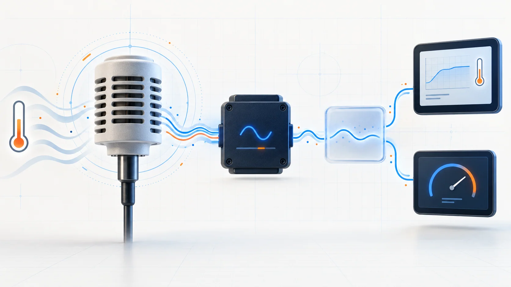
The ambient air temperature (AAT) system gives the truck a measured outside-air reference. On the detailed 2025 F-150 5.0L application reviewed for this overview, the powertrain control module (PCM) reads the AAT sensor, the climate-control module filters that information, and the instrument cluster or center display presents the outside temperature to the driver.
The value is more than a number on the screen. The PCM monitors the electrical signal, while the vehicle also uses the temperature information and its validity status across several modules. A fault can therefore appear as an implausible outside-temperature display, dashes in place of a value, or a powertrain DTC even when the engine otherwise seems to run normally.
The public STEP DTC guides linked below cover the 2015-2025 Ford F-150 5.0L Coyote Gas vehicle group. Detailed system-operation and diagnostic evidence for this overview was verified on the exact 2025 F-150 4WD 5.0L application. Sensor location, module routing, connector identification, thresholds, scan-tool functions, and repair procedures can vary with model year, equipment, drivetrain, and calibration. Use current service information for the exact truck being repaired before applying exact values or opening a circuit.
How the system turns outside temperature into a display value
The sensor and circuit create an electrical measurement
The AAT sensor is connected to the PCM through separate input and return circuits. The PCM supplies a reference and watches the voltage change that results as sensor resistance changes with outside-air temperature. The controller converts that electrical relationship into a temperature value.
This means the sensor is only one part of the measurement. An open wire, excessive circuit resistance, short to ground, short to voltage, poor terminal fit, water intrusion, corrosion, or damaged connector can create an extreme-looking temperature without the air actually being extremely hot or cold.
The value passes through a filtered data path
On the verified 2025 application, the PCM sends ambient-temperature data to the HVAC module. The HVAC module filters the data and sends the outside-temperature status to the instrument panel cluster and center display. If the status is briefly missing or invalid, the display can retain the last received value. If the condition lasts long enough, the display can show dashes instead of a temperature.
That module path matters diagnostically. A correct sensor signal at the PCM does not automatically prove that the displayed value will be correct. The HVAC module, network communication, instrument cluster, and center display can affect what the driver sees.
Filtering prevents a normal heat-soak condition from looking like weather
When a truck sits after driving, heat from the engine, radiator, pavement, and nearby structure can make the air around the sensor warmer than the true outdoor temperature. The system uses a filtered update strategy so that this local heat does not immediately become the displayed weather value.
The verified strategy considers engine-off time, engine temperature, sensed temperature direction, and vehicle speed. A rising reading may update slowly at low speed and more quickly as road speed increases, while a falling reading can update sooner. For that reason, a display that changes gradually after a hot restart is not automatically faulty. Diagnosis should compare the scan value, actual conditions, and display behavior under a valid operating condition.
What P0072 and P0073 are telling you
| DTC | Diagnostic direction | What it directs you to prove |
|---|---|---|
| P0072 | AAT sensor signal is below the monitor's accepted electrical range | Whether the sensor, signal/return circuit, connector, wiring, or responsible module is pulling the signal below the self-test minimum |
| P0073 | AAT sensor signal is above the monitor's accepted electrical range | Whether an open or high-resistance path, connector fault, sensor problem, short to voltage, or responsible module is pushing the signal above the self-test maximum |
“Low” and “high” describe the monitored electrical signal, not a confirmed outdoor temperature. P0072 does not automatically mean the weather is cold, and P0073 does not automatically mean the weather is hot. Neither code is an instruction to replace the sensor.
A companion range/performance code, communication code, HVAC code, display-module code, or voltage concern may change the diagnostic priority. Scan the relevant modules before isolating one component.
What the driver or technician may notice
Possible observations include:
- a malfunction indicator lamp with little or no drivability complaint;
- an outside-temperature display that is implausibly high or low;
- a display that remains fixed, changes only after driving, or intermittently shows dashes;
- an AAT scan value that disagrees sharply with actual outside conditions after a valid soak;
- a complaint that began after front-end, harness, connector, battery, HVAC-module, network, cluster, or center-display work;
- a fault that appears with rain, washing, temperature change, vibration, or harness movement;
- related communication, voltage, climate-control, or display DTCs.
Display delay by itself is not failure proof. Confirm whether the system is responding according to its heat-soak strategy before disturbing components.
Common failure categories
Airflow obstruction or physical damage near the sensor
Dirt, mud, debris, damage, or another obstruction around the sensing area can prevent free airflow or expose the sensor to a misleading local condition. Begin with the actual sensor area for the exact truck; do not assume a location from another model year or equipment package.
Connector, terminal, or water-entry problem
Water intrusion, corrosion, bent pins, pushed-out terminals, weak terminal tension, damaged seals, or a connector that is not fully latched can change the signal or make the fault intermittent. Inspect both halves without spreading terminals or damaging seals.
Open or high-resistance circuit
A broken conductor, weak splice, backed-out terminal, abrasion, or partially separated wire can interrupt the input or return path. The system may then report a high-side electrical fault or an implausible temperature. A visual inspection alone does not prove circuit integrity.
Short to ground, short between circuits, or short to voltage
Pinched wiring, rubbed insulation, previous probing damage, water entry, or contact with another circuit can pull the signal outside its monitored range. Isolate components and modules in the order specified by current service information before continuity or short testing.
Sensor resistance out of specification
The sensing element can be electrically biased, intermittent, or open. A resistance result is meaningful only when compared with the correct temperature and exact service table, with the circuit safely de-energized and the sensor isolated as directed.
Module or communication responsibility
The PCM reads the sensor, but the displayed value also depends on the HVAC module and the communication path to the display. Module replacement belongs at the end of a proof-based process, after powers, grounds, communication, connectors, sensor response, and circuit integrity are established.
A practical system-first diagnostic strategy
1. Preserve the original evidence
Confirm the exact year, engine, drivetrain, equipment, calibration, recent repairs, and current service information. Save a complete module scan, code status, failure records or freeze-frame data, AAT PID, relevant voltage data, displayed temperature, actual outdoor temperature, engine-off time, engine temperature, vehicle speed, and complaint conditions before clearing codes or resetting learned values.
2. Check related modules and code priority
Review PCM, HVAC, instrument-cluster, center-display, voltage, and communication faults. A shared power, ground, network, or module issue can affect the display without a failed AAT sensor. Follow the current service-information priority when several codes are present.
3. Validate the complaint under meaningful conditions
Compare the PCM AAT value with actual outside temperature after a suitable soak. Account for sun load, hot pavement, underhood heat, recent operation, low vehicle speed, and the normal filtered update strategy. Do not condemn the sensor from a hot restart or from the display alone.
4. Inspect the sensing area and connector
Check for debris, damage, restricted airflow, water entry, corrosion, pushed-out or bent terminals, weak locks, disturbed routing, sharp-edge contact, and evidence of recent work. Photograph routing before disassembly and use terminal-safe tools.
5. Prove the sensor and both circuit paths
Use the exact diagram and procedure for the truck. When directed, compare sensor resistance with the correct temperature table, then isolate and test the input and return circuits for opens, excessive resistance, shorts to ground, shorts between circuits, and shorts to voltage. Never substitute a generic connector view or threshold from another year.
6. Separate PCM input from display-path problems
If the PCM AAT PID agrees with actual temperature but the display remains wrong, move downstream through the HVAC status, network path, cluster, and center display as current service information directs. If the PCM PID is wrong, stay with the sensor, connector, input/return circuits, and PCM branch until the cause is proven.
7. Consider controller responsibility last
Before considering a PCM or another module, verify correct powers, grounds, connector seating, terminal condition, communication, and circuit response. Check current service information for applicable service messages or programming requirements. A module is not proven bad because the wiring looks intact.
8. Verify the complete repair
Restore seals, locks, routing, retainers, and any removed components. Clear codes or learned values only when directed, repeat the relevant self-test, and confirm that the PCM AAT value agrees with actual conditions. Verify the display through an appropriate update condition and re-scan all relevant modules. A cleared lamp or one plausible reading during a brief idle is not repair verification.
Repair categories
The confirmed result may support one or more of these repair categories:
- removal of debris or correction of damage that interferes with airflow at the sensor;
- terminal, connector, seal, splice, or harness-routing repair;
- repair of an open, excessive-resistance, short-to-ground, cross-circuit, or short-to-voltage condition;
- AAT sensor replacement when the isolated sensor fails the directed temperature/resistance test;
- correction of a PCM input problem after sensor and circuit proof;
- HVAC, network, instrument-cluster, or center-display communication or module service when the PCM value is correct but the displayed path is not;
- programming or module replacement only after all directed prerequisites are satisfied.
Do not choose the repair from the DTC title or displayed temperature alone.
Safety and service cautions
Turn the ignition off and follow the current procedure before disconnecting the sensor or control modules. Never measure resistance on an energized circuit. Use terminal-safe probes and do not force oversized test leads into connectors. Avoid piercing insulation unless the approved procedure specifically requires it, and seal any authorized test point correctly afterward.
Running-engine or road-speed verification can place the technician near moving fans, belts, pulleys, hot parts, and traffic. Secure clothing, hair, tools, and leads; keep hands and wiring away from moving or hot components; and use a second person or data recording when vehicle movement is required. Do not watch a scan tool while driving.
Final takeaway
The Ford F-150 ambient-temperature system is an electrical measurement and a filtered, multi-module information path. On the verified 2025 5.0L application, the PCM reads the AAT sensor, the HVAC module filters the data to control heat-soak effects, and the cluster or center display presents the outside temperature.
P0072 and P0073 identify opposite electrical-range failures; they do not identify a replacement part and do not prove the actual weather. Preserve the original evidence, account for normal display filtering, scan every relevant module, inspect the sensing area and connector, prove the isolated sensor and both circuit paths, and separate a PCM-input fault from a downstream display-path fault. Finish by reproducing the applicable self-test and display update condition, then confirm that the scan value, displayed value, DTC state, and original complaint are all resolved.