The engine controller needs more than a throttle request: it needs believable information about the air entering the engine. On the 2011–2022 Ford F-250 Super Duty 6.2 gas engine, airflow, throttle position and intake-air temperature help the PCM interpret operating conditions. A mismatch between signals and an electrical temperature-input fault are different problems, even when both appear as poor drivability.
This overview explains the air-information side of engine management. It is not a throttle actuator repair procedure or a fuel-pressure diagnostic guide.
Applicability and configuration boundaries
The named 2011–2022 F-250 Super Duty 6.2 gas-engine range is the vehicle family covered here. Service information was checked at the 2011 and 2022 endpoints. This supports a conceptual family overview, not identical sensor packaging, wiring, calibrations or test sequences across every year. The earlier source configuration is flex-fuel; the overview does not extend that fuel compatibility to every vehicle in the range.
Confirm the actual model year, engine, emissions configuration and installed components before testing. Use the applicable service information for sensor location, connector identification, meter reference points, expected readings, scan-tool commands and self-test conditions. A shared engine-control document can describe sensor arrangements and diagnostic branches that do not apply to the truck being repaired.
What the air-information system does
The intake tract supplies filtered air through its housing, ducts and connections toward the throttle body and engine. The physical path matters as much as the sensor readings: a loose connection, restriction or leak can change the relationship between measured airflow and the air actually reaching the cylinders.
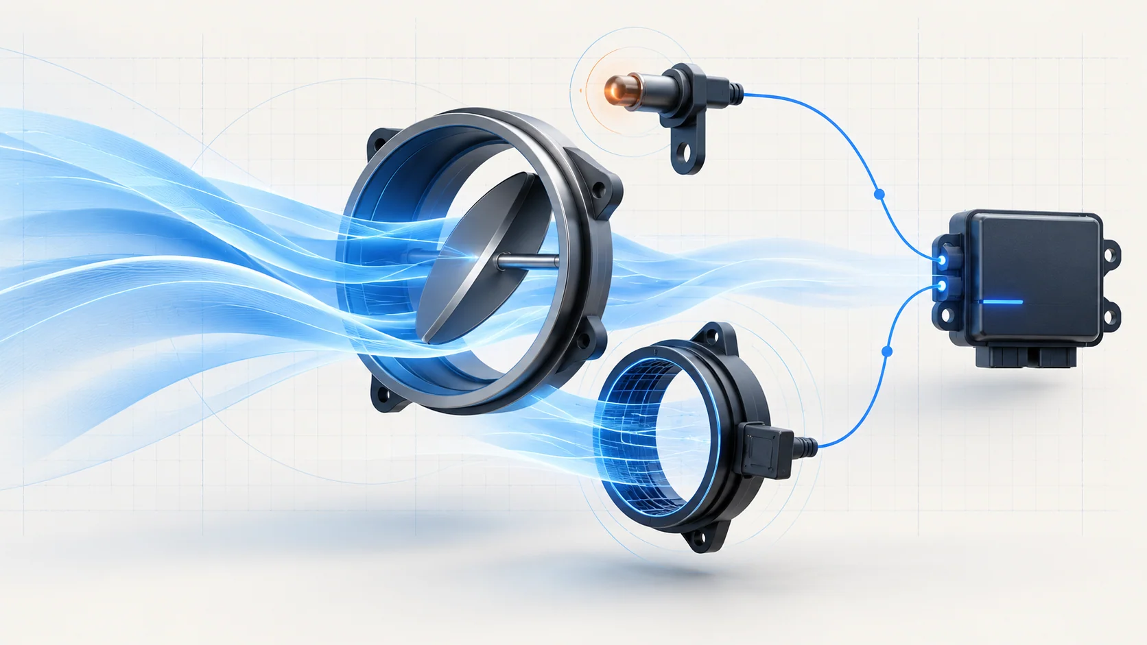
Mass-airflow information describes the incoming air quantity used by the controller. Throttle-position information reports the position of the throttle mechanism. Intake-air temperature provides another operating-condition input used in fuel, spark and airflow calculations. These inputs answer different questions; one plausible reading does not validate the others.
At idle, the later endpoint description also explains adaptive airflow control: the PCM considers airflow and throttle angle and can compensate for a change in expected airflow. This is a control strategy, not evidence that an air leak or restricted passage has been repaired. Resetting adaptive memory may require relearning and can remove useful diagnostic context.
Correlation is a relationship, not a failed-part verdict
The controller can compare throttle position with airflow and calibrated load expectations. A correlation fault means that the relationship did not meet the relevant plausibility check. It does not say which input, air-path condition or mechanical behavior caused the disagreement.
An intake or PCV leak may upset the relationship. A biased airflow signal, throttle-position circuit problem, poor connection or throttle obstruction may also require investigation. Distinguish an air-path defect from an electrical fault before replacing a sensor or throttle body.
Do not substitute accelerator-pedal position for measured throttle position. A driver request and the throttle's reported position are not the same evidence. Protective control strategies can also affect throttle response, so limited power is a symptom to investigate, not proof of a jammed throttle plate.
How the temperature input works
An intake-air temperature sensor uses a temperature-dependent resistance. In the thermistor description reviewed for this overview, resistance decreases as temperature increases. The circuit converts this change into an electrical signal the PCM interprets as temperature.
Keep physical temperature, signal voltage and the displayed temperature PID separate. A circuit-high DTC does not mean the intake air is physically too hot. An implausible reading can arise from the sensor, connector, signal path or return path; determine the applicable circuit behavior before deciding which component is responsible.
The sensor's packaging is not a universal fact for this year range. Use the exact vehicle information to establish whether the temperature element is part of a combined assembly and which circuits belong to it. Do not transfer another configuration's pinout or assume that every sensor named in a shared description is installed on this truck.
Two STEP guides, two diagnostic directions
P0068: airflow-to-throttle plausibility
The P0068 MAP/MAF–throttle correlation guide introduces the relationship between throttle-position information and airflow or load expectations. Intake connections and the PCV path deserve inspection alongside signal and connector integrity.
The code title names a correlation category; it does not establish a particular sensor inventory. Follow the actual application. The linked guide also flags an ambiguous continuation when P0068 is present alone and the named companion-code branch does not apply. Do not force that branch or invent the next test: obtain the complete applicable diagnostic route before proceeding.
Where the manufacturer-directed sequence calls for a self-test, follow its conditions. Do not operate the accelerator during a self-test unless the applicable instructions explicitly require it. A test performed under the wrong conditions can create misleading evidence.
P0113: intake-temperature circuit high
The P0113 diagnostic guide concerns the intake-temperature signal being electrically higher than expected. Treat it as a circuit-diagnosis direction before considering sensor or PCM replacement.
The guide identifies missing reference or second-lead information in some measurement and jumper descriptions. Those are real limits, not permission to guess. This overview supplies no substitute jumper connection. Verify the complete circuit diagram and test setup, including the return and component isolation requirements, before energizing or measuring anything.
Symptoms and a practical diagnostic strategy
Possible symptoms include an illuminated malfunction indicator, unstable idle, reduced throttle response, limited power or intermittent drivability changes. Some faults may be noticed mainly in scan data. Symptoms alone cannot distinguish leakage, temperature-input failure and throttle-position disagreement.
- Preserve the full code set, captured conditions, relevant PIDs and recent service history before clearing codes or resetting memory. Note whether the complaint began after intake, filter, sensor or harness work.
- With the system made safe, inspect filter-housing assembly, ducts, clamps, hoses and connectors. Check for disconnected or damaged parts and restrictions without assuming that an external visual inspection proves the entire air path sealed.
- Classify the evidence. For P0068, investigate the relationship among air path, airflow and throttle information. For P0113, establish the temperature circuit's integrity and whether the displayed data is plausible for the actual conditions.
- Compare readings under controlled, equivalent conditions using the applicable reference information. Heat soak and changing operating conditions can affect temperature comparisons; use the prescribed stabilization conditions rather than declaring a sensor faulty from an arbitrary difference.
- Use the exact directed electrical or air-path tests to separate the candidate causes. A stable sensor PID does not prove the absence of a leak, and a repaired leak does not prove a temperature circuit is sound.
- If the concern is intermittent or the next branch is unclear, preserve the evidence and resolve the applicable test route. Do not turn an incomplete test into a parts recommendation.
Repair categories and verification
Repairs may include restoring a correct intake connection, repairing a demonstrated air leak, correcting a restriction according to the applicable procedure, restoring a connector or circuit, or replacing a component that fails the relevant test. Throttle cleaning, sensor replacement and module replacement are not automatic consequences of either code. Use only approved handling methods for sensing elements and throttle components.
After a proven repair, restore all connections and repeat the specified self-test and relevant data checks. Safely reproduce the original complaint conditions where appropriate. Confirm that the affected signals behave plausibly and that no new related fault was introduced. Perform adaptive reset or relearn only when called for by the actual procedure. A cleared warning lamp alone is not repair verification.
Safety and component protection
Keep fingers and tools away from the electronic throttle mechanism; it can move with substantial force. Follow the specified ignition and power-state precautions before removing ducts, handling connectors or approaching moving mechanisms. Do not force the throttle plate or apply battery power to a signal circuit.
Keep test leads and clothing clear of fans, belts and hot surfaces, and ventilate any engine-running work area. Use suitable probes and approved test equipment without damaging terminals. Do not road-test a truck with unsafe throttle response or limited control simply to make a fault return.
The diagnostic aim is agreement between physical airflow, the controller's inputs and the actual operating conditions. Establish which part of that evidence is unreliable before choosing a repair.