Fuel control has to match the air entering the engine with fuel delivered to each cylinder. On the 2011–2022 Ford F-250 Super Duty 6.2 gas engine, an apparent lean bank, an injector circuit fault and a cylinder misfire are related possibilities, but they are not interchangeable diagnoses. Separate mixture feedback, electrical injector control and combustion quality before choosing a repair.
Applicability comes before testing
This overview covers the named 2011–2022 F-250 Super Duty 6.2 gas-engine family. Endpoint service descriptions identify sequential multi-port injection on the earlier configuration and port fuel injection on the later configuration. That supports the educational description here, not identical wiring, calibration or test procedures throughout the range. The earlier source configuration is flex-fuel; do not assume every truck has the same fuel compatibility or learning strategy.
Identify the actual model year, engine, emissions configuration and fuel specification before testing. The applicable service information controls connector identification, pressure limits, scan-tool routines, monitor conditions, component locations and repair procedures. A shared diagnostic chart may contain branches for engines or fuel systems that are not fitted to this truck. Do not apply a direct-injection pump test merely because it appears in a related fuel-control guide.
What the system does
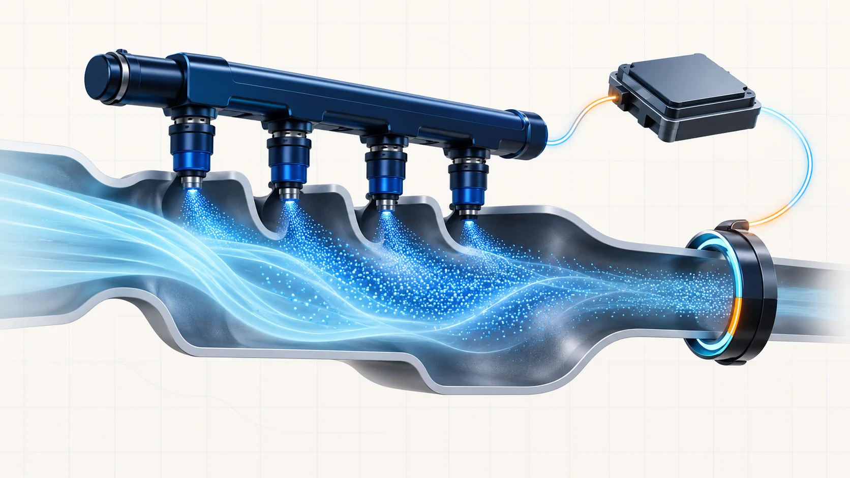
The fuel supply makes fuel available to the rail, and the injectors meter it into the intake ports. The PCM controls injector opening duration in response to engine demand. Airflow measurement and operating-condition inputs help establish the initial fuel command; exhaust oxygen feedback helps refine the mixture when closed-loop operation is active.
Think of three connected functions:
- Air estimation: the controller needs a useful representation of the air entering the engine.
- Fuel delivery and metering: supply and injector operation must turn the command into delivered fuel.
- Feedback: exhaust sensing and learned corrections help compensate for a persistent difference between the expected and observed mixture.
An electrical command is not proof of correct injector flow. Likewise, a lean indication does not identify an oxygen sensor as the failed part.
How mixture correction works
Short-term fuel trim represents the immediate correction, while long-term trim reflects learned correction. Positive correction generally means the controller is adding fuel relative to its base calculation; negative correction means it is removing fuel. Interpret trims with fuel-system status, engine temperature, speed, load and the operating conditions that triggered the complaint.
Compare both banks under comparable conditions. A bank-specific pattern and a pattern affecting both banks can guide different checks, but neither proves a particular component. Unmetered air, inadequate fuel delivery, incorrect airflow information, exhaust leakage affecting feedback, purge influence or a feedback-circuit problem can all require consideration. A misfiring cylinder can also complicate the exhaust evidence; do not diagnose mixture from one isolated trim reading.
Fuel composition is another context item on a verified flex-fuel application. Confirm the permitted fuel and applicable learning procedure before attributing a correction to fuel composition or resetting learned values.
Three DTC categories that should stay separate
P0171: bank-one lean fuel-control evidence
The P0171 diagnostic guide introduces a lean bank-one concern. Preserve captured conditions and investigate the air, fuel and feedback paths. Inspect intake ducting, hoses and connections before moving into the applicable controlled tests. A lean code alone does not justify replacing a sensor, injector or pump.
The linked guide includes shared diagnostic branches. Use only the branch confirmed for the truck being repaired; its exact values and commands are not universal specifications for this year range.
P0201: cylinder-one injector electrical control
The P0201 diagnostic guide concerns the cylinder-one injector circuit. Here the evidence directs attention toward supply, the control circuit, connector integrity, injector electrical condition and commanded operation. Check related codes before selecting the applicable circuit branch.
Distinguish a circuit fault from a flow restriction. Proving power and a control pulse does not prove the correct amount of fuel reaches the cylinder; a flow concern does not automatically explain an electrical DTC. Use the specified equipment and current circuit information rather than applying power or grounding a PCM-controlled wire experimentally.
P0301: cylinder-one combustion contribution
The P0301 cylinder-one misfire guide addresses the combustion result. Fuel delivery is only one possible cause. Ignition faults, compression or other mechanical concerns, air leaks and signal-related detection issues also belong in the investigation.
Confirm the weak cylinder with the applicable contribution or misfire data, then separate ignition, mechanical and fuel causes. A power-balance result identifies contribution, not the failed component. On this engine family, include the applicable spark-plug wires and boots in ignition inspection rather than assuming an injector is responsible for every cylinder-specific complaint.
A practical diagnostic strategy
- Record the complaint, all relevant codes, freeze-frame data and recent repair or refueling history before clearing anything. Note whether the fault appears at idle, during starting or under load.
- Establish a safe mechanical and electrical baseline. Inspect intake connections, accessible hoses, injector connectors and harness condition. Deal with an active fuel leak before running further tests.
- Classify the evidence: bank mixture correction, injector circuit operation or weak-cylinder combustion. Related codes may change which applicable test comes first.
- Reproduce conditions only when safe. Compare bank feedback at equivalent operating states and use the manufacturer-directed air-leak, fuel-delivery or circuit test to distinguish competing explanations.
- For a cylinder-specific concern, use the applicable ignition, contribution, compression and injector tests to establish cause. A successful electrical test and a successful mechanical-flow test answer different questions.
- Repair the demonstrated fault and repeat the relevant checks under the original conditions. If the concern cannot be reproduced, preserve the evidence and use the intermittent-diagnosis path instead of replacing parts speculatively.
Symptoms and repair categories
Possible symptoms include rough idle, hesitation, uneven power, starting difficulty or an illuminated malfunction indicator. A mixture code may also appear without a strong drivability complaint. Symptoms overlap, so use them to reproduce the concern rather than to name the failed part.
Repair categories include sealing a proven air leak, correcting a supply problem, restoring a damaged connector or circuit, replacing an injector that fails the applicable test, correcting a verified feedback concern, or repairing an ignition or mechanical cause of misfire. Module replacement is not a first response to these codes.
Verification is more than an extinguished warning light. Check for leaks after fuel-system work, confirm relevant data and cylinder contribution, repeat the specified self-test and safely reproduce the original operating conditions. Clear codes or reset adaptive memory only when the applicable procedure calls for it; doing so early can erase useful evidence.
Safety before opening or energizing the system
Fuel may remain pressurized with the engine off. Follow the applicable pressure-relief and fuel-handling procedure, keep ignition sources away, provide ventilation and use approved containers and protective equipment. Do not loosen a connection as a pressure test.
Keep leads, clothing and hands clear of moving components and hot exhaust surfaces. Use approved injector and ignition test equipment; do not disconnect ignition components with the engine running or improvise jumper tests on module circuits. A flashing malfunction indicator with severe misfire is a catalyst-damage warning: stop loading the engine and investigate safely rather than continuing a proving drive.
The useful starting point is the category of evidence. Establish whether the PCM is correcting the bank mixture, failing to control an injector circuit, or detecting poor cylinder combustion, then use the exact vehicle procedure to find out why.