Turbocharger boost control helps match the engine's air supply to its operating requirements. On the F-250 Super Duty 6.7 Power Stroke diesel, low boost and a turbocharger position-control concern are related diagnostic subjects, but they are not the same failure. Neither a power complaint nor a turbo-related code proves that the turbocharger assembly needs replacement.
This educational introduction covers STEP's 2011–2025 F-250 Super Duty 6.7 Power Stroke Diesel library. Early and late source configurations support that model-and-engine scope, not identical turbochargers, actuators, wiring or calibrations throughout the range. Match the actual year, engine variant, configuration and emissions package before selecting a procedure. Component locations, connector terminals, limits and service actions remain vehicle-specific.
Purpose and operation
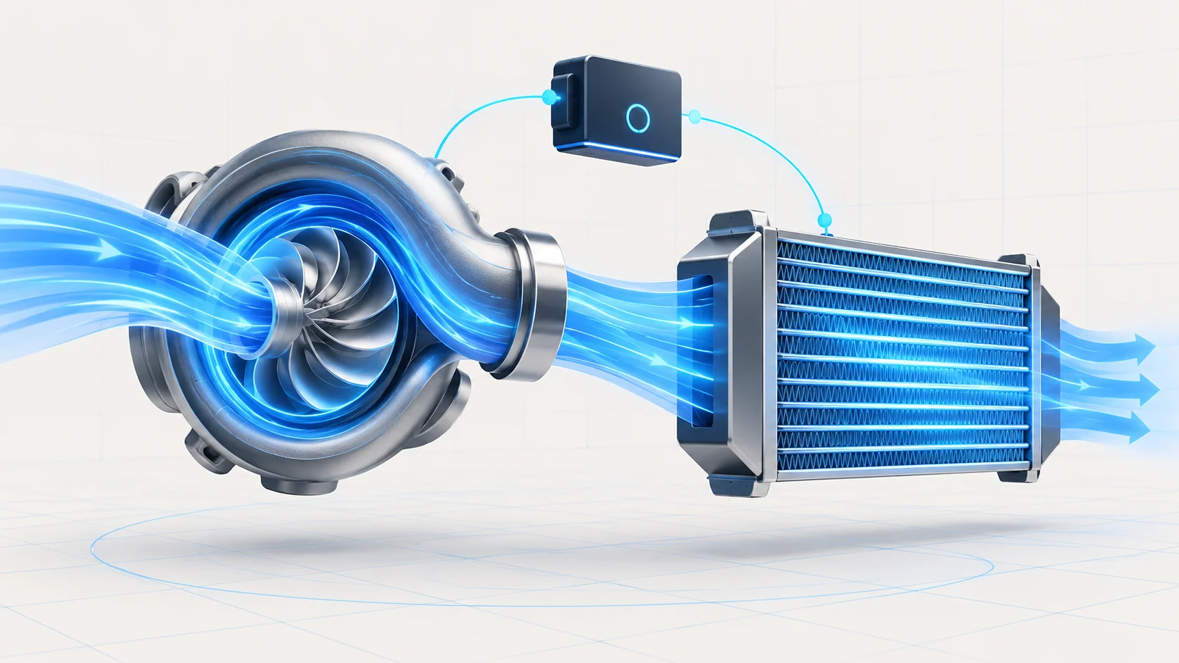
The compressor raises the pressure of incoming air. Compression also heats that air, so the charge-air cooler helps reduce its temperature before it reaches the engine. The late-endpoint operating description explains that cooling the pressurized air increases its density. The air path and its connections therefore belong in boost diagnosis, not only the turbocharger itself.
The late-endpoint system uses variable turbocharger geometry controlled by an actuator. Its control is closed-loop: the powertrain control module (PCM) receives feedback and adjusts actuator position in response to engine speed, load, manifold pressure and barometric pressure. The aim is boost appropriate to the engine's requirements, not one pressure value under every condition.
Keep three kinds of evidence separate: what the controller requests, what the position feedback reports, and what pressure the air system actually produces. An apparently responsive actuator does not certify that the charge-air path is sealed. A pressure mismatch does not independently identify whether the cause is air loss, operating context, an input concern or turbocharger control.
This overview does not specify actuator technology, vane geometry, plumbing layout or a common position scale for every model year. Use the installed system's description before interpreting a command or feedback parameter.
How the related guides fit
P0299 Diagnostic Guide introduces an underboost concern: the controller sees less boost than expected under the applicable conditions. Treat the code as a performance observation. It does not, by itself, distinguish a leak, restriction, control problem or misleading input.
P2598 Diagnostic Guide introduces turbocharger position-control performance. The late-endpoint diagnostic description identifies a stuck-low performance concern using calibrated relationships among control and position information. Do not interpret “low” as a universal physical arm position or as proof of a failed actuator.
Use the complete code and subtype with the actual vehicle's diagnostic definition. These guides organize the investigation; their exact values, commands and connector details are not specifications for the entire catalog range. An unclear branch or an unavailable prerequisite requires the applicable service information, not a guessed continuation.
Failure categories and symptoms
Start by separating air-path integrity from control and measurement integrity. Leaks between the turbocharger and intake manifold can affect delivered air. Restrictions, disturbed connections or other intake and exhaust conditions can also matter in the appropriate diagnostic path. A sensor can report a real performance problem without being its cause.
On the control side, investigate connections, circuit integrity and the applicable supply, return and feedback paths. Position information, manifold-pressure information and actuator response each need their own supporting checks. Mechanical sticking or binding is another category, but it must be established through the correct inspection rather than inferred from a code alone.
The driver may report reduced power, slow acceleration or derate behavior, and the malfunction indicator lamp may be illuminated. Such symptoms are not unique to boost control. Preserve the complete code pattern and do not force a fuel, electrical or other engine concern into a turbocharger diagnosis merely because the truck feels weak.
A practical diagnostic strategy
Record the complaint, operating state, full code list and available failure data before clearing anything. Review recent repairs and disturbed charge-air or electrical connections. Establish the basic battery, charging and engine-condition context, then follow the applicable direction for related circuit and system codes.
Inspect accessible ducts, joints, hoses, wiring and connectors with the engine safely stopped. Look for actual damage, poor installation, contamination or a connection concern. Use the specified leak-test method when required; do not invent a pressure limit or apply unregulated shop air to the system.
Use scan data to compare requested behavior, position feedback and pressure under the prescribed conditions. A stationary or unloaded test does not automatically reproduce a load-related underboost complaint. Conversely, an output-control response does not prove normal performance across the operating range. Interpret each result only for what that test demonstrates.
Regeneration is important context. The late-endpoint procedure warns that it can bias diagnostic values. Identify whether it is occurring and follow the applicable procedure before judging the data; this overview does not authorize initiating a regeneration or defeating emissions controls.
If electrical testing is required, identify the exact circuit, meter reference, power state and adapter first. Resistance measurements need the prescribed isolation. Do not apply power or ground directly to a module-controlled component unless the correct procedure explicitly requires it. Protect terminals from unsuitable probes.
Repair categories and verification
Repair the demonstrated defect, whether it is an air-path connection, wiring, terminal, sensor, actuator or confirmed mechanical turbocharger concern. Actuator feedback and mechanical movement are not interchangeable evidence. Do not force a linkage, alter an adjustment or replace the turbocharger simply because a commanded test is inconclusive.
Removal, installation, lubrication requirements and any learning or reset function must come from the exact service procedure. Do not prescribe one reset sequence across all years. Restore every disturbed connection and check that the original complaint, relevant data and codes have been addressed under safe, applicable conditions.
Clearing codes or observing one successful actuator movement is not a complete repair verification. Save the post-repair evidence and re-evaluate an intermittent or load-related concern under conditions that actually exercise it.
Safety and scope
Let turbocharger and exhaust components cool before access. Follow the required isolation procedure, prevent unintended starting or commanded actuator movement, and keep hands and tools clear of moving mechanisms. Never place fingers in the intake or compressor area while the system can operate.
Secure the vehicle, provide exhaust ventilation and use approved support for work underneath it. Release any test pressure safely before disconnecting equipment. A road test must not require the driver to watch a scan tool or reproduce an unsafe load. Stop if abnormal mechanical noise or another serious condition makes continued operation unsafe.