Applicability and purpose
This overview applies to the 2014-2018 GMC Sierra 1500 with the 5.3-liter gasoline V8. Vehicle records confirm the model and engine at both ends of that range, while the detailed operating and diagnostic evidence used here comes from a 2018 Sierra 1500 4WD V8-5.3L.
Use this article to understand how the air/fuel feedback loop fits together before opening a code-specific test. Calibration values, connector details, sensor locations, scan-tool commands, and repair procedures can vary. The applicable service information for the truck being repaired controls those details.
What the system is trying to control
The engine control module (ECM) must deliver enough fuel for the air entering each cylinder, then check the combustion result and correct its command. It does this with a control loop rather than by trusting one sensor or one calculated value.
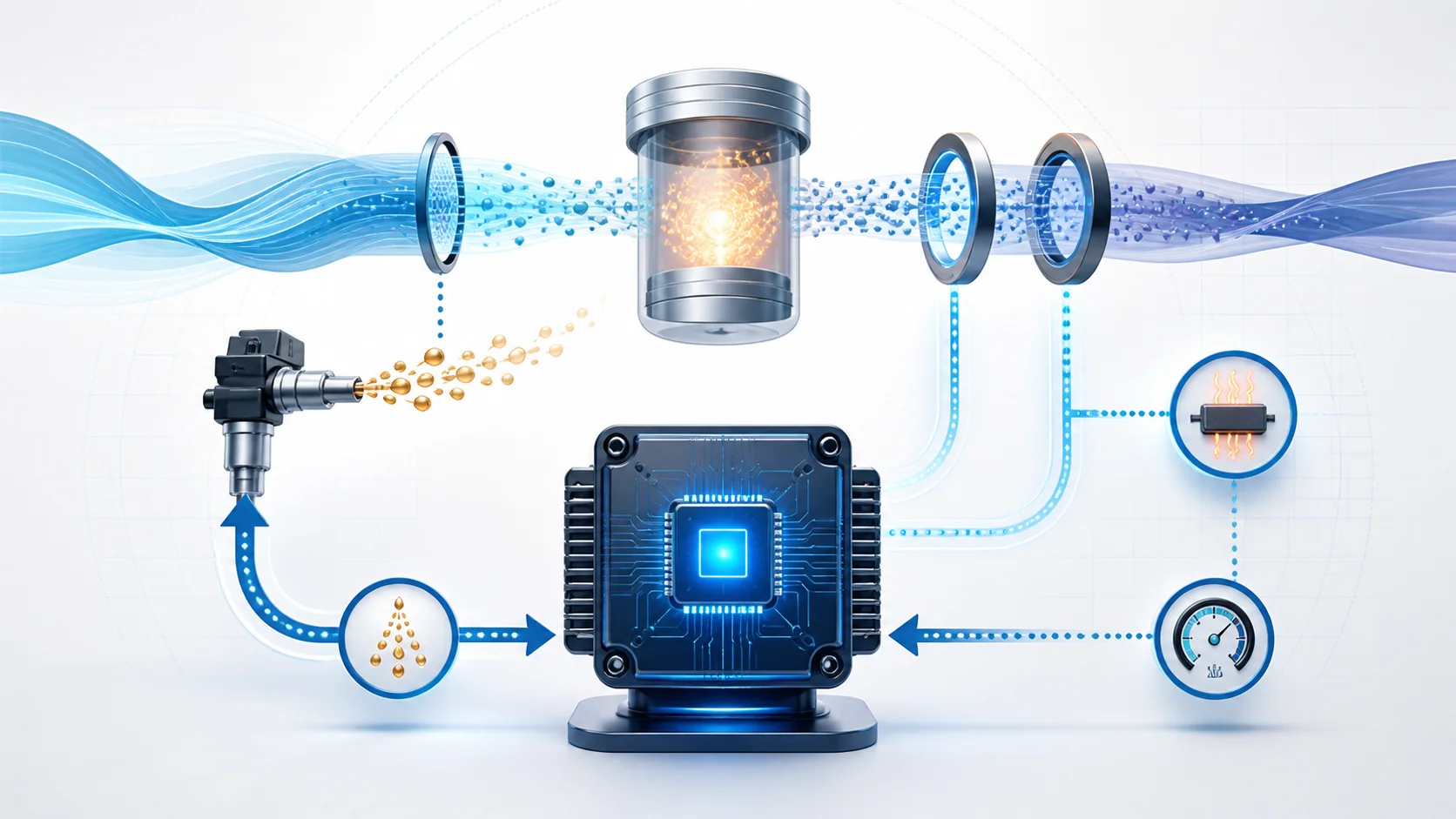
The basic sequence is:
- airflow, manifold pressure, throttle position, temperature, engine speed, and other inputs describe the operating condition;
- the ECM calculates a starting injector command;
- fuel-pressure feedback helps the ECM judge whether the delivery system can support that command;
- the injectors meter fuel into the cylinders;
- heated oxygen sensors report the oxygen content left in the exhaust;
- the ECM adjusts injector on-time and records the direction and amount of correction as fuel trim.
This distinction matters in diagnosis. An oxygen sensor reports what it sees in the exhaust, but it does not by itself identify why the exhaust is lean or rich. Likewise, a fuel-trim DTC describes a control result outside the expected range; it does not prove that an oxygen sensor, injector, pump, or airflow sensor has failed.
Open loop, closed loop, and sensor readiness
During starting and some other operating conditions, the ECM calculates fueling without using normal oxygen-sensor feedback. This is open-loop operation. Once the required operating conditions are met and the relevant sensor signals are usable, the ECM can enter closed loop and use exhaust feedback to fine-tune fuel delivery.
Heated oxygen sensors include heater circuits so the sensing elements can reach a useful operating temperature sooner. A heater fault can delay or disrupt feedback readiness even when the engine seems to run normally. That is why a heater code should be treated as an electrical readiness problem, not automatically as proof that the sensor's measuring element is inaccurate.
On this application, the oxygen sensors do not all serve the same diagnostic role. Upstream feedback is central to mixture control. A downstream sensor provides post-catalyst information used for monitoring and plausibility. A high downstream signal can reflect an electrical fault, a sensor problem, or a genuine operating condition. Bank and sensor position must therefore be identified before interpreting scan data.
How fuel trim records the ECM's response
Fuel trim is the ECM's correction to its calculated fuel command.
- Positive trim means the ECM is adding fuel because feedback indicates that the base command is too lean.
- Negative trim means the ECM is removing fuel because feedback indicates that the base command is too rich.
- Short-term fuel trim responds quickly to current feedback.
- Long-term fuel trim represents a broader learned correction developed from recurring short-term behavior.
A number near the center of the correction range is not proof that every component is healthy. The condition may not be active, one correction may be masking another, or the engine may be operating in a different load cell from the one that produced the DTC. Freeze-frame data and repeatable operating conditions are more useful than an isolated idle snapshot.
Bank comparison is also important on a V-engine. A similar correction on both banks often points toward something shared, such as measured airflow, fuel supply, purge flow, or a common operating input. A strong difference between banks more often focuses attention on a bank-specific intake leak, exhaust leak, injector or cylinder condition, or sensor path. That is a diagnostic direction, not a parts verdict.
What the related DTCs contribute
| DTC | Monitored behavior | What the mechanic must prove |
|---|---|---|
| P0135 | Bank 1 Sensor 1 heater circuit does not behave as expected | Whether the power feed, control circuit, connector, heater element, or ECM driver explains the fault before replacing the sensor |
| P0138 | Bank 1 Sensor 2 signal is higher than expected | Whether the signal is genuinely reporting a rich exhaust condition or is being forced high by the circuit, connector, sensor, or controller path |
| P0171 | Bank 1 learned mixture correction has moved too far lean | Why the ECM is adding fuel: unmetered air, incorrect measurement, inadequate delivery, exhaust influence, purge/ventilation flow, cylinder performance, or another cause |
| P0191 | On the detailed 2018 application, the two pressure outputs within the fuel pressure and temperature sensor disagree | Whether the sensor channels and their low-reference, 5-volt reference, and serial-data paths are believable; P0191 does not by itself prove that actual fuel pressure is low or high |
| P0201 | Cylinder 1 injector control circuit is open or otherwise electrically abnormal | Whether the injector, wiring, connector, or ECM control path is at fault; the circuit code alone does not prove an injector flow problem |
These guides belong in one diagnostic picture, but they answer different questions. Resolve electrical faults that can corrupt feedback or delivery before using fuel trim to condemn a mechanical component.
Common ways the control loop can fail
Unmetered or incorrectly measured air
An intake leak, crankcase-ventilation leak, purge-flow problem, damaged duct, sealing fault, contaminated sensing element, or skewed airflow or pressure signal can make the ECM's calculated air charge disagree with reality. The resulting trim may be most visible at idle, under load, or during a particular purge condition.
Fuel delivery or injector problems
Low-side supply, high-pressure generation, pressure regulation, contaminated fuel, restriction, leakage, or injector flow can move the mixture away from the command. Electrical injector faults are a separate category from restricted or leaking injectors. Fuel-pressure data must also be judged for plausibility before it is treated as proof of real pressure.
Oxygen-sensor readiness, signal, or exhaust influence
A heater circuit can prevent timely sensor readiness. A signal circuit can be open, shorted, resistive, or contaminated by poor terminal contact or moisture. Exhaust leakage can introduce oxygen and make the feedback appear lean. A genuinely rich or lean exhaust condition can also produce a believable sensor response even though the root cause is elsewhere.
Ignition and mechanical engine faults
Incomplete combustion changes oxygen content in the exhaust. Compression loss, valve-train problems, ignition faults, or cylinder sealing issues can therefore influence fuel trim and oxygen-sensor data. Do not assume every lean indication is caused by insufficient gasoline.
Wiring, power, grounds, and module inputs
Heater feeds, low-reference circuits, sensor references, signal circuits, injector drivers, grounds, and connectors can fail continuously or intermittently. A shared reference or power fault may affect several values at once. Module replacement belongs at the end of a proven test path, not at the beginning.
What the driver or technician may notice
Depending on the fault and when it occurs, the truck may have only a malfunction indicator lamp. It may also show rough idle, hesitation, reduced power, hard starting, an intermittent misfire, changed fuel economy, fuel odor, or a complaint that appears only at a particular temperature or load.
Symptoms overlap heavily. A heater code may have little immediate drivability effect. A circuit fault may disable an injector and create a strong cylinder complaint. A trim code may appear after the ECM has compensated for a subtle air or fuel problem for some time. Use symptoms to reproduce the condition, not to skip testing.
A practical diagnostic strategy
1. Capture evidence before clearing anything
Record all modules' DTCs, status, freeze-frame or failure records, fuel trims by bank, loop status, oxygen-sensor data, pressure data, temperature, load, engine speed, and battery voltage. Note whether the complaint happened at idle, cruise, acceleration, hot restart, cold start, or during refueling.
2. Establish code priority
Handle power, ground, reference, communication, heater, and clear circuit faults that can invalidate mixture data before diagnosing the final fuel-trim result. An active injector circuit fault or implausible pressure signal can explain why trim is abnormal.
3. Confirm the engine is ready for interpretation
Verify normal operating temperature, closed-loop status when required, stable charging voltage, and believable sensor values. Do not interpret a cold open-loop snapshot as if the ECM were actively correcting from oxygen feedback.
4. Compare banks, loads, and time
Observe short- and long-term trim at more than one stable condition. Compare banks and watch how the correction changes when airflow and load change. Use the pattern to decide whether the fault is shared, bank-specific, load-dependent, or intermittent.
5. Prove the air path
Inspect the induction system, intake sealing, vacuum hoses, crankcase ventilation, and purge connections. Test for leaks with an appropriate method. Compare airflow, manifold pressure, throttle position, and temperature evidence for agreement rather than judging one PID alone.
6. Prove fuel delivery and injector control
Separate commanded pressure from believable measured pressure and from actual delivery capacity. Follow the applicable low- and high-pressure tests when the evidence points there. For a cylinder-specific concern, distinguish injector command, circuit integrity, injector flow, ignition, and mechanical sealing.
7. Prove the exhaust-feedback circuit
Identify the correct bank and sensor. Check heater operation, power and control integrity, terminal condition, routing, and signal response with the applicable service procedure. Inspect for exhaust leaks before deciding that a lean response proves a bad sensor.
8. Verify the repair under the failure conditions
After correcting the proven cause, complete any required reset or learn procedure from the applicable service information. Recreate the relevant temperature, load, and time window; confirm the DTC does not return; and verify that trims and sensor behavior remain believable. A cleared code at idle is not a complete repair verification.
Repair categories and safety
Repairs may involve sealing an intake, crankcase-ventilation, EVAP, or exhaust leak; restoring a heater, reference, signal, ground, or injector circuit; repairing terminals or harness routing; correcting fuel supply or pressure control; servicing an injector; replacing a sensor that failed its test; or correcting ignition or mechanical engine faults.
Allow hot exhaust parts and oxygen sensors to cool before service, and support the exhaust when required. Keep sparks, flame, and hot tools away from gasoline and vapor. Relieve fuel pressure with the applicable procedure before opening the system, contain spilled fuel, ventilate the work area, and use eye protection. Never use an unfused jumper or improvise a circuit test around an ECM driver.
The best repair is the one supported by the evidence chain: captured failure conditions, a repeatable symptom or failed test, correction of the cause, and successful verification afterward.