A catalyst-efficiency code is a monitor result that needs context, not an instruction to install a converter immediately. On the GMC Sierra 1500 5.3 gas engine, the engine control module evaluates exhaust-sensor information under defined operating conditions to judge catalyst performance. Sensor readiness, circuit integrity, exhaust condition and engine operation all matter to that judgment.
This overview covers the conventional 2014–2018 GMC Sierra 1500 5.3 gas configuration. It does not cover eAssist electrical service or establish identical calibrations, sensor circuits or service procedures for every build. Engine-specific information at both ends of the range supports the conceptual explanation. The exact vehicle's service information controls bank identification, sensor selection, monitor conditions, specifications, test connections and repair verification.
What the catalyst does
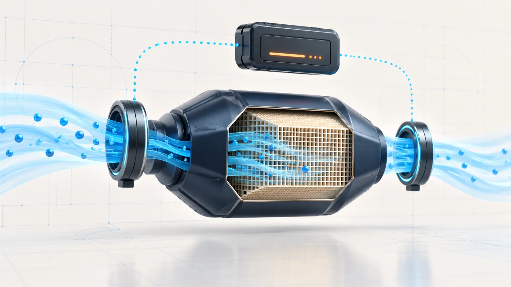
The three-way catalyst helps reduce harmful exhaust emissions. Its active material promotes reactions that convert hydrocarbons and carbon monoxide into water vapor and carbon dioxide and reduce nitrogen oxides to nitrogen. It also stores oxygen, a property the control system can evaluate as part of judging conversion performance.
The converter is therefore more than an exhaust restriction or a container around a sensor. Its ability to process exhaust depends on its physical condition and on what the engine sends into it. An engine-running fault can damage a catalyst; correcting the converter alone may leave that cause in place.
How monitoring differs from normal fuel feedback
Heated oxygen sensors before and after the catalyst provide information about exhaust oxygen. Upstream information is important to fuel feedback, while the downstream response contributes to catalyst evaluation. This article focuses on that evaluation, not on interpreting learned fuel-trim corrections.
On the endpoint applications examined for this overview, the catalyst diagnostic uses a suitable off-idle deceleration fuel-cut event. A healthy catalyst's oxygen-storage behavior makes the post-catalyst response slower than the pre-catalyst response during the defined test. A downstream response that approaches the upstream response can indicate reduced storage capability. That relationship must be judged within the applicable diagnostic strategy, not from two arbitrary traces at idle.
A single sensor reading is not a direct measurement of tailpipe emissions. Likewise, one similar-looking waveform is not enough to select a replacement part. The monitor needs valid input signals and the prescribed operating conditions before its result is meaningful.
Sensor readiness and signal integrity come first
An oxygen sensor must reach a useful operating temperature before its signal can be interpreted properly. Its heater helps shorten warm-up and maintain the required operating state. A heater-circuit fault can therefore undermine readiness even if the engine appears to run normally.
The heater and the sensing circuit are separate diagnostic questions. Power supply, a fuse, wiring, terminals, the heater element and the control path can affect heater operation. A signal that is high can reflect a real exhaust condition, an electrical fault or a sensor problem. “Circuit high” does not, by itself, prove a rich-running engine or a failed converter.
Identify the correct bank and sensor before evaluating data. Do not infer physical location, a terminal assignment or a test connection from a generic label or the illustration. Code availability and diagnostic families also vary with year and equipment; a broad library title is not proof that one code-specific procedure applies unchanged to every truck.
What the linked STEP guides contribute
| STEP guide | Diagnostic role | Important boundary |
|---|---|---|
| P0420 — catalyst-efficiency guide | Follows the Bank 1 catalyst-monitor result into the relevant physical checks and repair verification. | A monitor that has not produced a valid result is not a failed catalyst test. |
| P0135 — oxygen-sensor heater guide | Explains a heater electrical diagnosis and why feed/control checks precede a sensor verdict. | Confirm the exact year's code and heater procedure; do not apply its thresholds or connections to a different diagnostic family. |
| P0138 — Bank 1 Sensor 2 signal-high guide | Separates signal-circuit evidence from a sensor or engine-operating-condition conclusion. | A high signal is not a catalyst-efficiency verdict and does not justify replacing the converter. |
These guides answer different questions. Resolve faults that can invalidate the monitor or its inputs before treating the catalyst result as an isolated component diagnosis.
Read the test state and the result separately
The useful sequence is to establish that the test's conditions are met, observe it running, establish completion and then read the result for the correct bank. The state and result are not interchangeable.
| Observation | What it establishes |
|---|---|
| Conditions not met | The required test opportunity has not been established; it says nothing conclusive about converter health. |
| Active | The monitor is running, not yet a repair verdict. |
| Transition to Inactive after the monitored test | Check the test counter and reported result to establish what the completed attempt produced. An Inactive snapshot alone is not proof that a test ran. |
| Passed or Failed | A usable result for that test attempt; interpret it with the applicable diagnostic path and bank. |
| No Result | An inconclusive attempt, not a pass and not a failure. Re-establish the prescribed conditions safely as directed. |
Scan-tool wording and available parameters depend on the application. A cleared code, an extinguished warning light or an incomplete readiness monitor does not demonstrate that catalyst performance has passed verification.
Failure categories and symptoms
The truck may have only a malfunction light, with little obvious drivability change. Other symptoms can come from a contributing engine or exhaust problem rather than from catalyst efficiency alone.
- Catalyst deterioration or damage: degraded active material, damaged substrate, overheating, impact damage or restriction require the appropriate inspection and testing.
- Exhaust-system problems: leaks, damage, restriction or loose hardware can affect the diagnostic picture. Leak and restriction are different findings and need different proof.
- Sensor or circuit problems: heater readiness, signal integrity, damaged connectors, harness faults or sensor condition can prevent reliable evaluation.
- Engine conditions that harm the catalyst: misfire, incorrect mixture, weak ignition, or excessive oil or coolant consumption can contribute to degradation. Identify and correct the cause rather than installing another converter into the same conditions.
- An incomplete test opportunity: the required operating state may not have occurred. This is a verification gap, not a component failure category.
A practical diagnostic strategy
- Capture the evidence before clearing codes. Record the complete faults, status and available event data. Confirm the exact engine and equipment, relevant bank and complaint history, including engine-running problems or abnormal fluid consumption.
- Deal with prerequisite faults. Follow the applicable priority for heater, sensor-signal, engine-control and misfire concerns. Do not use suspect input data to condemn the converter.
- Establish a safe, valid test opportunity. Use the vehicle-specific monitor instructions. Road speed, temperature, load and other conditions are monitor gates, not universal service values or permission to drive unsafely.
- Observe execution and outcome. Distinguish conditions met, Active, completion and the bank-specific result. Check the counter or other completion evidence. Do not turn No Result into a pass or fail.
- Follow the failed-result inspection path. Evaluate the converter, exhaust system and relevant downstream sensor as directed. Look for physical damage and contributing engine faults; do not replace a sensor merely because it reports what the exhaust is doing.
- Repair the proven cause and complete required setup. The repair may be exhaust integrity, wiring, sensor service, an engine fault or a converter that fails its applicable diagnosis. Sensor learning or reset requirements are vehicle-specific, not a universal shortcut.
- Verify performance, not just code clearing. Restore removed components and complete the specified setup. Re-run the relevant monitor under safe prescribed conditions and obtain a valid result for the affected bank. If the result remains inconclusive, verification is not complete.
Safety and repair boundaries
Exhaust components and sensors can remain hot after shutdown. Allow the required cooling time, use eye protection and follow safe lifting and support procedures before working underneath the truck. Never rely on a jack alone. Use suitable exhaust extraction for running tests; do not run the engine in an enclosed space without it.
Severe misfire can overheat a converter. Reduce load and stop safely if the warning light flashes with severe rough running; do not repeatedly provoke the condition to force a monitor result. Arrange diagnosis or recovery when continued operation is unsafe.
Use properly rated electrical test equipment and the exact circuit procedure. Do not improvise jumpers, bypass sensor circuits, install signal simulators or disable monitoring to hide a fault. For driving verification, record data safely or use another technician; do not watch scan data while driving or disregard road conditions to satisfy a test window.
The diagnostic goal is a complete evidence chain: trustworthy inputs, a valid monitor opportunity, a known result, a supported repair and a successful post-repair check. That chain is more useful than a converter replacement based on the code name alone.