Automatic climate control needs useful information about the conditions it is trying to manage. A temperature or sunlight sensor circuit fault can make climate operation inconsistent, but a code naming a sensor does not prove that the sensor itself has failed.
This educational overview covers climate-control sensor inputs in the 2010–2017 Honda Accord 2.4 Gas family. Direct service evidence was reviewed for a 2010 Accord 2.4 and a 2017 Accord Sedan 2.4 with the relevant climate-control equipment. Equipment, control units, connectors, self-diagnostic indications, and test order differ across configurations. The endpoint evidence does not establish identical circuits or procedures for every intervening year or trim. Confirm the fitted system and use the applicable service information for exact specifications, circuit identification, test conditions, and repair procedures.
What the inputs tell the controller
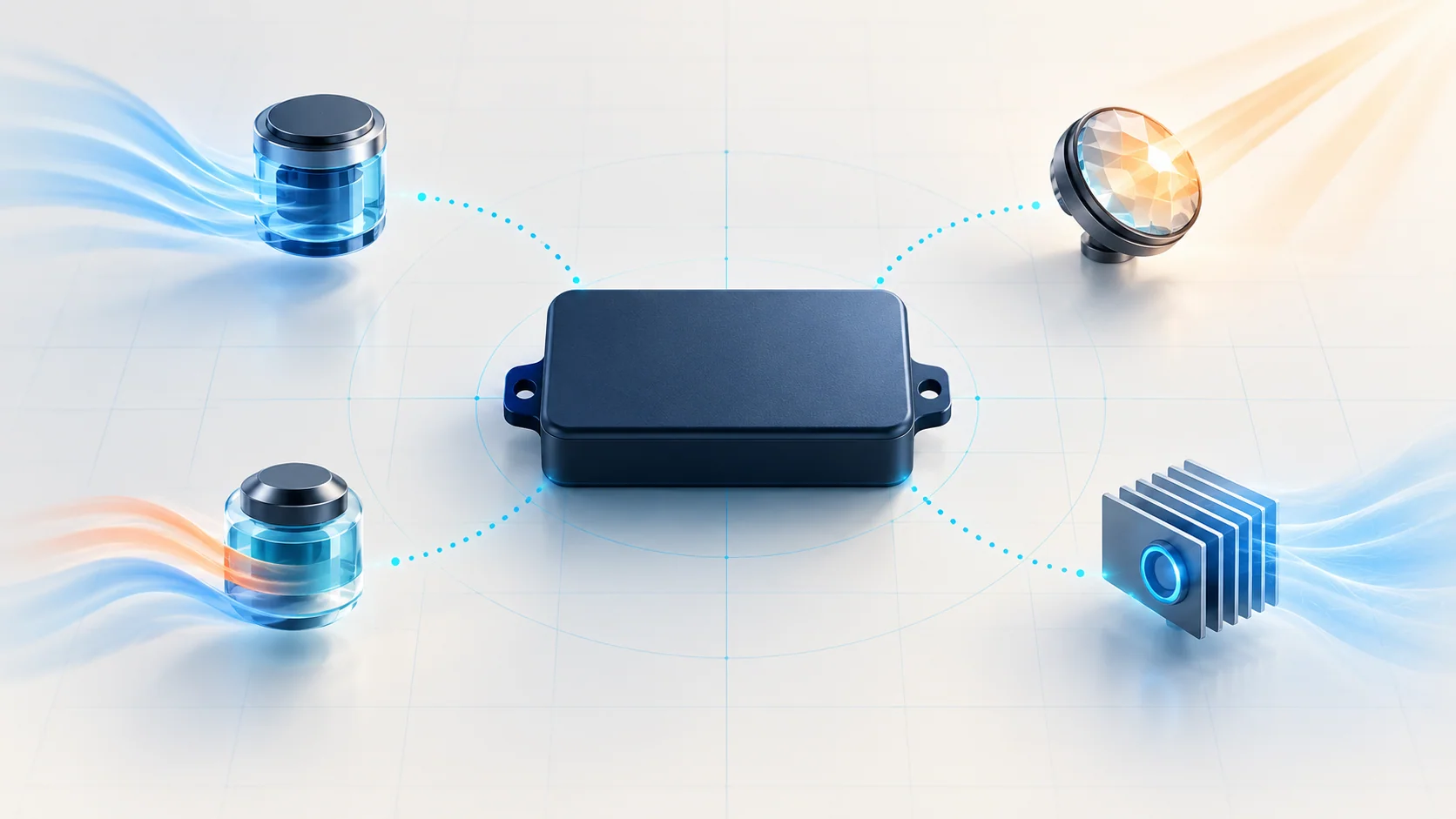
The selected temperature is a request. The sensor inputs provide information used by the climate system to respond to conditions. Four useful categories are:
- In-car temperature: information about the cabin's thermal condition. The reviewed sensor test evaluates its electrical response under prescribed temperature conditions.
- Outside air temperature: information about ambient conditions. A circuit problem can affect the temperature information available to the climate system and may accompany an incorrect outside-temperature indication.
- Sunlight: information related to solar load. This is a light-sensitive input, so its test conditions differ from those of a temperature sensor.
- Evaporator temperature: information associated with the A/C evaporator. A usable temperature signal is relevant to cooling operation; an electrical circuit code does not, by itself, establish a refrigerant-pressure or charge problem.
Keep those inputs distinct when reviewing scan data or the complaint. Cabin temperature, outside temperature, and evaporator temperature describe different conditions and need not be equal. A sunlight response also depends on the illumination used during the check. Record the operating conditions before interpreting a reading.
How the published DTC guides fit
| STEP guide | Diagnostic category |
|---|---|
| B1225 — B1225 Diagnostic Guide | In-car temperature sensor circuit open concern. Identify the correct sensor and circuit before making a component decision. |
| B1228 — B1228 Diagnostic Guide | Outside air temperature sensor circuit short concern. Distinguish the sensor from wiring and connection faults. |
| B1229 — B1229 Diagnostic Guide | Sunlight sensor circuit open concern. Complete the applicable circuit and light-response checks before condemning a part. |
| B1231 — B1231 Diagnostic Guide | Evaporator temperature sensor circuit open concern. Follow the applicable signal-path, return-path, and sensor checks. |
| B1232 — B1232 Diagnostic Guide | Evaporator temperature sensor circuit short concern. Keep its fault path separate from the open-circuit branch. |
An open or short description classifies an electrical concern. It is not a direct measurement of the real temperature or sunlight load, and it is not a replacement instruction.
Common failure categories and possible symptoms
An interrupted signal or return path. The reviewed open-circuit charts include the sensor wiring and the relevant return or common path. A disconnected terminal, damaged wire, or poor connection can therefore be a candidate as well as the sensor. Use the exact diagram to identify which paths apply.
An unintended electrical connection. The reviewed short-circuit paths distinguish a signal shorted to ground from a short involving another circuit. The circuits must be isolated as directed before a continuity result can be interpreted. Do not assume the same connector or common-circuit arrangement applies to every year.
A sensor response outside the applicable specification. A temperature sensor must be evaluated under the prescribed temperature conditions. The reviewed sunlight test also specifies the illumination conditions; an improvised workshop light is not automatically an equivalent substitute. A reading taken under the wrong conditions can lead to a false component decision.
A controller-side concern after the directed checks. Some reviewed paths reach a climate-control-unit decision only after other checks pass. The early and late endpoint procedures do not use one universal test order. Follow the exact chart rather than transplanting a later vehicle's sequence or replacing a controller because several sensor codes are present.
Possible complaints include inaccurate or inconsistent automatic temperature control, an incorrect ambient-temperature indication, poor response to solar load, or inconsistent cooling. A stored code may also appear without an obvious complaint. These symptoms are not guaranteed on every vehicle and can have causes outside the input circuits.
A practical diagnostic strategy
- Identify the fitted climate system and complaint. Confirm the year, equipment, affected function, and recent work. Record whether the concern changes with temperature, sunlight, vehicle operation, or time.
- Save the initial code picture. Use a capable tool with access to the relevant climate system. Record all related faults before clearing them. An engine-only code reader may not provide the necessary body-system access.
- Confirm the fault using the applicable self-diagnostic routine. The reviewed procedures use a prescribed power cycle and climate self-diagnosis before checking whether the fault returns. Do not assume that self-diagnostic indicators or entry methods are identical across the range.
- Keep electrical fault classification and sensor plausibility separate. Follow the open or short branch for the identified input. Where supported, compare sensor data with the actual conditions, but do not use a plausible-looking value as proof that the circuit has passed all tests.
- Follow the vehicle-specific test order. Inspect connections and complete the directed circuit and sensor checks under the required isolation conditions. Use the correct temperature or illumination specification. Resolve related faults through the applicable diagnostic sequence.
- Verify the repair in two ways. Repeat the required code/self-diagnostic confirmation and check the climate behavior connected with the original complaint. A code that does not return during one check establishes only that the fault was not reproduced at that time.
This approach prevents a sensor code from becoming a parts-replacement shortcut. It also keeps an electrical input diagnosis from being confused with a complete evaluation of airflow, actuators, or the refrigerant system.
Repair categories and completion evidence
A supported repair may involve restoring a proven open, correcting a diagnosed short, repairing a poor connection, replacing a sensor that fails its specified test, or addressing a controller fault established by the applicable procedure. A wiring repair and a sensor replacement solve different failure categories; document the test that justified the chosen action.
After repair, record the operating conditions, the relevant input behavior, the self-diagnostic result, and whether the customer's original complaint was reproduced and corrected. Normal temperature control and absence of a returning DTC are distinct observations. For an intermittent concern, preserve the limits of the test instead of declaring a permanent repair from one successful check.
Safety around climate-control testing
Follow electrical isolation and restraint-system precautions before working around dashboard wiring and connectors. Do not probe unfamiliar SRS circuits or measure resistance through powered electronics. Keep clear of fans, belts, hot components, and moving climate-control mechanisms during operating tests.
Use the prescribed sensor-test method rather than improvised heating, wiring jumpers, or simulated signals. Do not open the refrigerant circuit simply because a temperature-input code is stored. Any refrigerant-system work requires the appropriate service equipment and safe recovery procedure. This overview supplies no substitute pinout, temperature curve, light source specification, or refrigerant-service instruction.