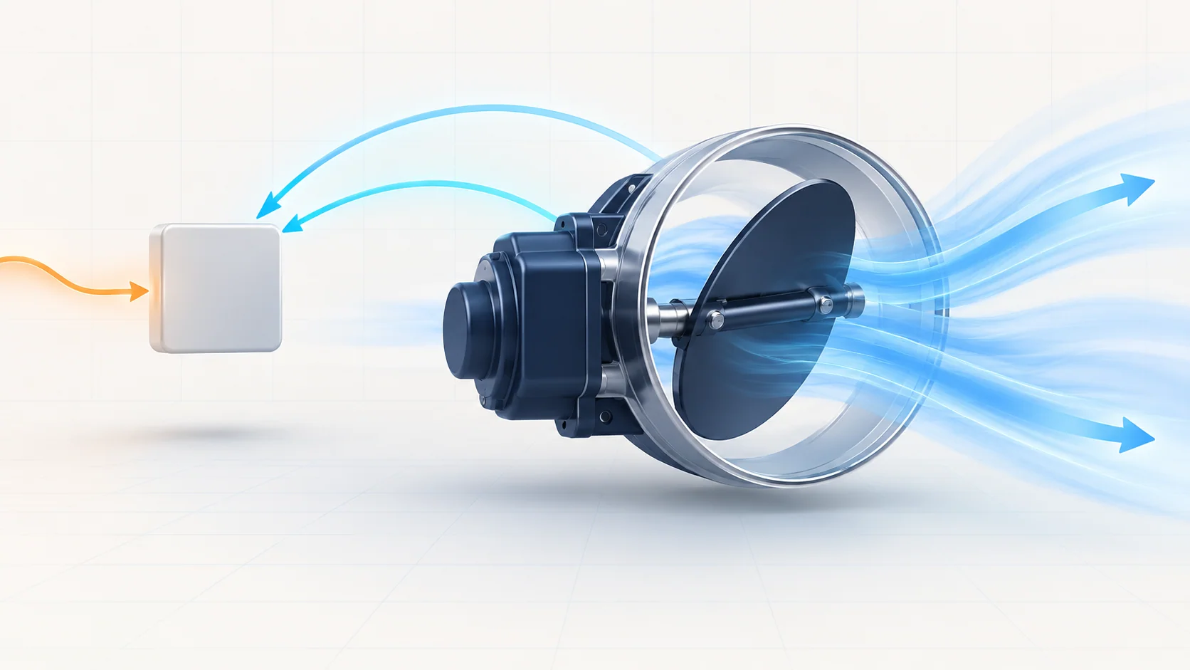
Electronic throttle control turns a driver's accelerator request into a controlled throttle-valve position. The accelerator pedal provides an input to the engine controller; an electric actuator moves the throttle, and position feedback lets the controller assess what actually happened. Power delivery, commanded movement and feedback agreement are related, but they are not the same diagnostic question.
This educational overview covers the 2010–2017 Honda Accord 2.4 gas vehicle profile. Sources at the first and last model years support the functional explanation, not identical engines, modules, relay arrangements, connectors, calibrations or repair procedures throughout the range. Confirm the exact engine, configuration and installed components. The applicable service information controls electrical limits, test conditions, component access, software work and repair verification.
How the system works
The main functional elements are the accelerator pedal position input, the engine or powertrain control module, the throttle actuator and valve, throttle position sensors A and B, and the electronic throttle control system power-supply path. Honda service information refers to the electronic throttle control system as ETCS.
The controller interprets the pedal input and determines a target throttle position, then operates the actuator to move the valve. Throttle position, or TP, feedback describes the valve's position; accelerator pedal position, or APP, describes the driver's pedal request. A pedal value is not a direct measurement of throttle-plate movement. Nor should pedal percentage and throttle percentage be assumed identical under every operating condition.
The two TP channels provide information whose relationship the controller monitors. Correlation does not mean that both channels must show the same voltage or percentage. Use the exact parameter definitions and diagnostic criteria rather than inventing a universal channel ratio or tolerance. A plausible single-channel reading does not prove that the pair agrees under the conditions that set a fault.
The actuator also needs the correct electrical supply. A control command, a relay's mechanical click, voltage at a monitored point and current available to an operating load are different observations. None should silently stand in for all the others.
Relay supervision and position correlation
| STEP guide | Diagnostic question | What it does not establish alone |
|---|---|---|
| P1658 — ETCS control relay ON malfunction | Does the observed ETCS supply behave as required when the applicable monitor expects it to switch off? | That the relay itself is defective, or that the title means the controller was commanding it on |
| P1659 — ETCS control relay OFF malfunction | Is the required ETCS supply present under the applicable activation or actuator-operation conditions? | Whether the cause is a relay, feed, connection, circuit or controller concern |
| P2135 — TP sensor A/B correlation | Do the two throttle-position signals maintain their specified relationship? | That the accelerator pedal sensor is faulty, or that cleaning or replacing the throttle body is already justified |
The ON/OFF wording describes the named malfunction; it is not a substitute for reading the monitor definition. In the examined P1658 descriptions, relay-supplied voltage remains present after switch-off. In the examined P1659 description, the expected supply is absent during the specified powered conditions. These are source-scoped explanations, not universal timing or voltage tests for every vehicle. Preserve the exact published guide URLs, but use the applicable service procedure for the actual test.
Failure categories and symptoms
A warning light may be the main complaint. Reduced or abnormal throttle response may also be reported, and an intermittent event can disappear before the vehicle reaches the workshop. Do not promise a particular protective mode, default throttle angle or remaining performance from the DTC name. Unsafe response requires a controlled workshop plan, not routine road reproduction.
Power-related categories include a relay that does not behave as required, an incorrect feed or output condition, an open or short in the relevant circuit, and poor terminal contact. Feedback concerns can involve the throttle-body assembly, its connections, or the specified signal circuits. The examined P2135 chart includes a check for an unwanted connection between the two signal paths. Software or controller-related work appears only in conditional diagnostic branches, not as a first replacement recommendation.
Mechanical condition and electrical feedback must remain separate. A valve that moves during one test does not prove correct signal correlation, while a correlation fault is not by itself evidence of dirt, a jammed plate or a bad pedal. Coexisting intake, engine-control or supply problems need their own evidence rather than being renamed throttle-body failures.
A practical diagnostic strategy
- Identify the application and preserve evidence. Record the exact vehicle, module identification, all codes and their status, freeze data and available snapshots before clearing anything. Note recent battery, relay, wiring, throttle or module work without assuming it caused the fault.
- Choose the correct question. Separate pedal request, target position, TP feedback and relay-supply behavior. Read parameter names, units and ignition or engine-state requirements. A scan command is not proof of the physical response.
- Distinguish current from intermittent. Follow the chart's prescribed reproduction and ETCS checks. If the fault does not recur, retain the original evidence and investigate the relevant connections; a normal reading now is not completed repair verification.
- Follow the exact electrical or component branch. Use the correct relay, feed, connector and signal definitions for the vehicle. Check circuit integrity and component operation only in the states the procedure specifies. Do not apply another model year's terminal numbers, bridge a relay socket or assume that a voltage reading proves loaded circuit capability.
- Treat module-related work as controlled. Software updates or a known-good comparison belong only to the branch that establishes their need. Confirm application compatibility and required setup. An arbitrary used PCM or throttle body is not a valid diagnostic substitute merely because it plugs in.
- Verify after the directed correction. Complete the applicable initialization or learning work when required, then repeat the prescribed checks and inspect pending and confirmed codes. Confirm that the original response concern is addressed. Clearing a code or completing one actuator sweep is not proof that the original failure condition has been corrected.
Repair categories and safety
The supported outcome may be a directed connection or circuit repair, replacement of a tested relay or throttle-body assembly, or a properly established software or module action. The diagnosis determines the category. This overview supplies no universal cleaning method, idle-learn sequence, relay bypass or module replacement procedure. Any required learning and verification belong to the exact application.
An electronic throttle can move during powered checks. Keep fingers, tools and test leads out of the bore and linkage area; do not force the plate or reach into it while power or a commanded test is possible. Follow the prescribed shutdown and isolation steps before access or connector work. Do not inject battery voltage into signal circuits or bridge unidentified terminals. Resistance checks require the specified unpowered and disconnected condition.
For running checks, ventilate exhaust and keep clear of belts, fans and hot components. Use the correct electrical support for authorized programming and do not interrupt it. Do not watch live data while driving; use safe recording or another technician where road verification is necessary and permitted. If throttle response is unsafe, keep the vehicle out of normal traffic until an appropriate assessment is complete.
What successful diagnosis establishes
A useful result connects the correct application, the recorded event, the expected electrical state, trustworthy position feedback and a supported repair. Keep commanded and observed behavior distinct, preserve the difference between APP and TP, and let the exact ETCS procedure decide what must be measured next. Final verification must address both the relevant codes and the original operating concern.