A headlight complaint does not always start at the lamp. Before checking why an output is dark, stuck on or inconsistent, establish whether the body electronics are receiving the driver's lighting request. On the 2010–2017 Honda Accord 2.4 gas family, switch-position information is an important diagnostic boundary: an incorrect input can send the investigation in a different direction from a failed lamp power supply.
Applicability comes before circuit testing
This overview covers the published 2010–2017 Accord 2.4 gas vehicle family. Endpoint service information supports the switch-input diagnostic concept, not identical equipment or procedures throughout that range. Confirm the actual year, body, trim, market and installed lighting system before selecting a wiring diagram or test.
Do not assume the same connectors, wire colors, control-unit arrangement or scan-tool sequence apply to every vehicle. AUTO selection, daytime running lamps, automatic high-beam features and lamp technology are configuration questions, not interchangeable descriptions of one circuit. The applicable service information for the vehicle being repaired controls exact values, commands, isolation steps and replacement requirements.
What the command side does
The combination light switch lets the driver select a lighting request. In the sourced diagnostic configurations, the MICU—the multiplex integrated control unit—receives switch-position information that can be inspected through the appropriate body-electrical scan data. This is an input to the control system, not a direct measurement of light emitted by a headlamp.
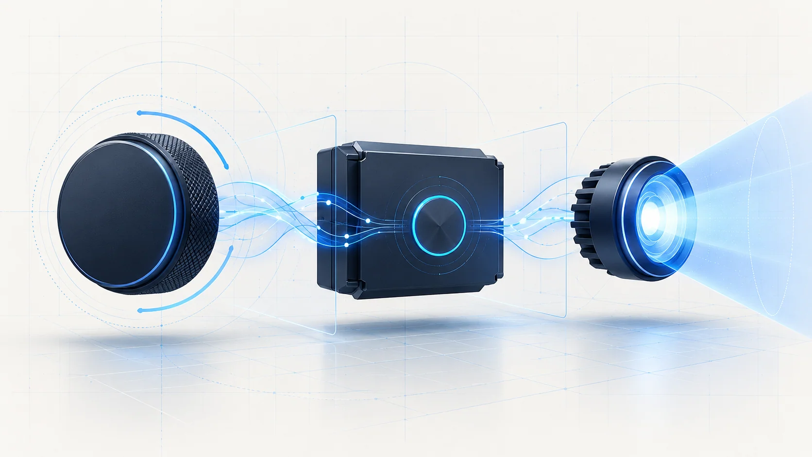
Think in three separate layers: the driver's selection, the input state recognized by the controller, and the resulting lamp operation. A selector can move normally while a signal path is faulty. A scan parameter can follow the selection correctly while a separate output-side problem remains. Observing one layer does not prove the other two are healthy.
How the linked codes fit
The linked guides address related switch-position circuit concerns:
- B1275: headlight switch position circuit malfunctions belongs to the OFF-position input category in the sourced diagnostic chart.
- B1276: headlight switch position circuit addresses the parking-position input category in that chart.
- B1278: MICU headlight switch position circuit malfunction belongs to the headlight ON-position input category.
Use the exact applicable DTC description and procedure rather than treating these labels as universal definitions for every Honda. A code identifies a failed behavior or circuit category; it does not identify a replacement part by itself. These guides introduce the input investigation, not a complete diagnosis of every exterior-lighting complaint.
Failure categories and possible symptoms
An input may remain asserted after the driver changes position, or fail to become active when expected. Depending on the confirmed configuration and fault, possible causes include switch contacts, a signal path shorted to ground, an open or high-resistance path, a related switch-ground circuit, connector condition or a controller-side problem. The direction of the wrong scan value matters because those categories do not share one universal test.
The driver may report lighting that does not match the selected position, inconsistent response or an intermittent concern. A technician may instead discover a stored body-electrical code while the lights appear normal. None of these observations alone establishes whether the fault is in the command side, the lamp output side or more than one area.
Start with observations, not replacement
Record the complaint, relevant DTCs and available scan evidence before clearing information. Establish which lamps or functions are affected and which selector positions reproduce the concern. Inspect accessible connectors and visible damage without disturbing unrelated circuits, and use the applicable basic electrical checks before interpreting abnormal data.
With a suitable scan tool, compare the recognized switch-position inputs with the driver's actual selections. Read parameter names carefully: an ON/OFF scan label describes that input's logical state, not necessarily whether the lamp should be illuminated. Use the vehicle's own expected-state information; do not invent a truth table from the word OFF or assume only one parameter can ever be active.
If the data is correct now, retain the intermittent possibility. Check relevant connection quality and try to reproduce the original conditions safely. A currently correct reading does not prove that a past fault was repaired.
Separate the switch, wiring and controller
When an input is wrong, follow the diagnostic branch that matches its direction. In the sourced strategy, an unexpectedly asserted input leads to a different isolation path from an input that remains inactive. Controlled separation of the switch from the circuit and the prescribed signal-response checks help distinguish the switch from the remaining wiring and controller path.
That principle is not permission to ground an unidentified wire. Do not substitute a generic jumper test for the exact service procedure. Verify the connector, circuit identity, power state and required disconnections before any directed test. Resistance or continuity checks require the isolation specified by the source; a result taken through connected electronics can be misleading or damaging.
Prove the relevant signal and ground paths before considering the MICU or a larger fuse/relay-box assembly. A single generic continuity reading is not a universal module verdict. If switch data is correct but physical lighting is wrong, move to the applicable output-side diagnosis instead of forcing the complaint into a switch-input code path.
Repair categories and verification
Repairs may involve restoring a connection, repairing a proven wiring or ground-path defect, replacing a confirmed faulty switch, or addressing a controller-side fault after the complete applicable diagnostic path. Follow the vehicle-specific replacement and setup requirements; do not replace a module merely because its name appears in a DTC title.
After repair, repeat the original switch-position observations and confirm the physical lighting response separately. Recheck DTCs through the applicable procedure and assess whether the intermittent conditions can be reproduced. Clearing a code, changing a scan value and restoring useful illumination are different pieces of evidence, not interchangeable definitions of success.
Safety boundaries
Do not drive in darkness or poor visibility with unreliable required lighting. Work safely around hot lamps and electrical loads, and identify the installed lamp technology before service; high-voltage equipment, if fitted, needs its own precautions. Switch-area access can be near SRS components: do not probe SRS circuits, and follow the applicable isolation procedure before disassembly. This overview supplies no bypass, pin-level jumper recipe or substitute for the manufacturer's safety instructions.
The useful diagnostic habit is simple: verify the request, verify the recognized input, then verify the output. Keeping those layers separate makes the linked B1275, B1276 and B1278 guides more useful—and reduces the temptation to replace a switch, lamp or control unit without proving the failed path.