Applicability basis: Exact vehicle records confirm 2018 Honda Accord Sedan Hybrid 2.0-liter applications with LFB1 and LFB2 engine variants and a 2025 Honda Accord Sedan Hybrid 2.0-liter LFC5 application. The detailed diagnostic and service evidence used for this overview was verified on the 2025 LFC5 target. Exact system design, pressures, scan-tool functions, monitor conditions, component locations, high-voltage isolation requirements, and repair procedures must come from service information for the vehicle being repaired.
What the fuel system does
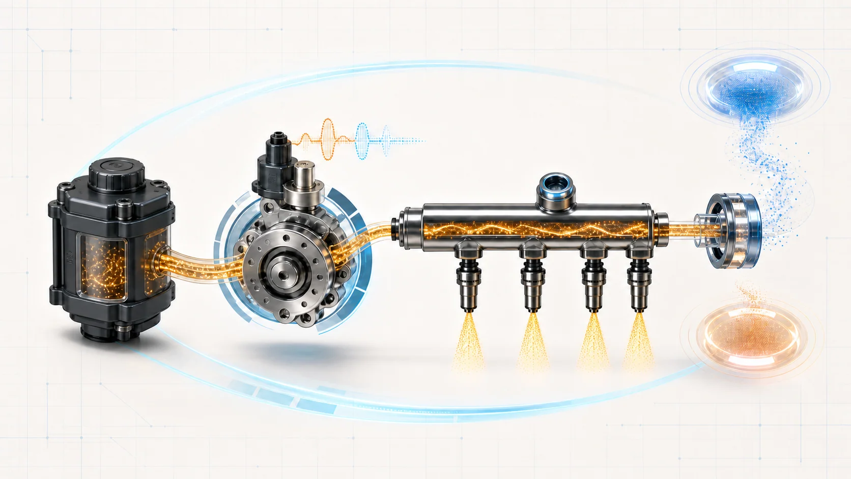
The fuel system must supply the 2.0-liter gasoline engine with the correct amount of fuel whenever the hybrid control strategy calls for the engine to run. The verified 2025 system uses direct injection: the in-tank side supplies fuel to a mechanically cam-driven high-pressure pump, the pump raises pressure for direct injection, the rail distributes fuel, and the injectors meter it into the combustion chambers.
Fuel delivery is only one part of the system. The PCM also evaluates whether measured rail pressure follows its target and whether combustion and exhaust feedback match the commanded fueling. Diagnosis therefore involves several connected functions:
- The low-pressure side must feed the high-pressure pump without leakage or restriction.
- The high-pressure pump, its mechanical drive, and its control solenoid must make rail pressure follow the command.
- The rail-pressure signal must be believable.
- The injectors must deliver the commanded amount consistently across all four cylinders.
- Airflow, air-fuel, and downstream oxygen-sensor feedback must let the PCM evaluate the result.
- Ignition, compression, intake, exhaust, EVAP purge, and base-engine condition must be sound enough that they do not imitate a fuel fault.
A DTC identifies a monitored behavior that failed. It does not automatically identify the component that must be replaced.
The main functional sections
Component design and location vary across the model-year range, but the diagnostic logic can be organized into these sections:
Because the endpoint evidence establishes model and engine availability but not identical fuel-system architecture, the component discussion below describes the verified 2025 LFC5 direct-injection system. Check the applicable service information before applying direct-injection or high-pressure-pump details to an earlier vehicle.
- Fuel tank, in-tank pump, and low-pressure lines: This side moves fuel toward the engine and must provide a sealed, adequate supply to the high-pressure pump.
- High-pressure pump and cam drive: The engine drives the pump mechanically. Pump output can be affected by fuel supply, pump control, internal pump condition, or the condition of the cam and follower that operate it.
- Fuel-control solenoid: The PCM controls the high-pressure pump through its fuel-control function. A command or circuit problem is different from a mechanical pressure-generation problem.
- Fuel joint pipe, rail, and rail-pressure feedback: The high-pressure path supplies the injectors, while the pressure signal lets the PCM compare commanded and actual behavior.
- Direct injectors: Each injector meters fuel into one cylinder. Electrical operation, sealing, flow, and cylinder-to-cylinder consistency can all affect the diagnostic result.
- PCM mixture control: The PCM combines operating conditions, airflow information, pressure feedback, and exhaust feedback to calculate pressure and injection commands.
- Upstream air-fuel and downstream oxygen feedback: These sensors give the PCM different views of mixture and catalyst-outlet behavior. Exhaust leakage or a primary engine fault can distort that evidence.
- Related engine and emissions systems: EVAP purge, air metering, ignition, compression, intake and exhaust condition, and fuel or oil contamination can change the measured air-fuel result even when the rail-pressure system is working normally.
How pressure control and mixture feedback work together
The low-pressure side feeds the high-pressure pump. The pump then supplies the rail according to operating demand, and the rail-pressure sensor shows the PCM how the system responded. The injectors convert that pressure and commanded on-time into cylinder fuel delivery.
Exhaust feedback provides another layer of evidence. Overall fuel trim shows whether the PCM is making an unusual mixture correction. Post-catalyst fuel trim evaluates downstream behavior after the catalyst. Cylinder air-fuel variation uses A/F-sensor-derived imbalance and learned fuel coefficients to identify a cylinder whose air-fuel behavior differs. The P2623 monitor evaluates fuel-control-solenoid driver current and circuit feedback against the electrical command.
These observations overlap, but they answer different questions:
- Rail-pressure data asks whether measured pressure follows the target.
- Fuel-trim data asks whether overall mixture control requires abnormal correction.
- Post-catalyst data asks whether downstream exhaust behavior matches expectation.
- Cylinder-variation data asks whether one cylinder's learned air-fuel behavior differs from the others.
- Pump-control monitoring asks whether solenoid-driver current and circuit feedback agree with the electrical command; it does not by itself measure hydraulic output.
The mechanic's task is to decide which failed behavior is primary and which is a consequence.
What the related DTCs are telling you
| DTC | Diagnostic category | What it directs you to prove |
|---|---|---|
| P0087 | Direct-injection pressure lower than target | Whether low-side supply, leakage, rail-pressure feedback, pump control, the pump drive, or the high-pressure pump prevents pressure from reaching the command |
| P0088 | Direct-injection pressure higher than target | Whether the pressure signal is credible and whether the high-pressure system can regulate pressure as commanded |
| P0172 | System-wide rich mixture correction | Whether fuel pressure, injector delivery, airflow information, purge flow, fuel-diluted engine oil or poor fuel, and air-fuel feedback explain the rich result |
| P2097 | Post-catalyst fuel trim too rich | Whether a primary mixture or cylinder fault, exhaust leakage or restriction, or sensor feedback explains the downstream rich-side deviation |
| P219E | Cylinder 3 air-fuel variation on the verified four-cylinder source | Whether cylinder 3 differs because of injector delivery, ignition, compression, or a local intake or exhaust condition after primary related faults are resolved |
| P2623 | High-pressure-pump fuel-control-solenoid electrical behavior does not match the driver command | Whether shared injector-relay supply, the external pump-control circuits, the solenoid integrated with the pump, or—only after those checks pass—the PCM-side driver explains the electrical disagreement |
This separation matters. One fuel-pressure result cannot explain every rich, downstream-feedback, cylinder-specific, or electrical-control DTC.
What the driver or technician may notice
The exact symptom depends on when the fault occurs. Possible observations include:
- a malfunction indicator lamp with few other symptoms;
- extended cranking, hesitation, reduced power, or a stall when pressure is inadequate;
- rough or uneven engine operation;
- a concern that appears only under conditions similar to the stored snapshot;
- related pressure-sensor, injector, ignition, misfire, air-fuel-sensor, or cylinder-variation DTCs.
Hybrid operation can make intermittent engine symptoms harder to reproduce because the gasoline engine does not run continuously under every operating condition. Use the applicable maintenance or diagnostic mode only as directed by service information, and do not treat an engine-off period by itself as proof of a fuel-system failure.
Fuel and hybrid safety come before diagnosis
Gasoline is flammable, and the direct-injection side can retain hazardous pressure after the vehicle is switched off. Never loosen a fitting to check whether pressure is present.
Work in a ventilated area away from ignition sources. Use the specified eye and hand protection, approved containment equipment, and the exact pressure-relief procedure before disconnecting a fuel line. Follow applicable service information for 12-volt battery disconnection before unplugging fuel-system electrical connectors. After line, pump, rail, or injector work, restore every connection and perform the specified leak inspection before normal operation.
This vehicle also contains a high-voltage electric powertrain. Fuel-system diagnosis does not automatically require high-voltage service, but any work that enters a high-voltage area or requires disabling the electric powertrain must follow the exact electric-powertrain and service-plug procedure, including the specified PPE, isolation, and verification steps. Do not improvise a high-voltage disable procedure from a general overview.
If liquid fuel leakage, damaged high-voltage components, or an uncertain vehicle safety state is present, stop and correct or escalate that hazard before continuing.
Failure categories represented by these DTCs
1. The high-pressure pump is not receiving an adequate supply
P0087 can begin upstream of the high-pressure pump. Low fuel level, an out-of-fuel event, a leak, restriction, weak supply, or another low-side problem can prevent the high-pressure stage from reaching its target.
This is why low rail pressure is not an automatic high-pressure-pump diagnosis. Prove the low-pressure supply under the conditions that produce the fault before judging pump output.
2. High-pressure generation or regulation cannot follow the target
The pump, cam drive, fuel-control solenoid, rail, pressure feedback, and control circuits work together. Pressure below target and pressure above target are opposite failure directions and should not be treated as the same diagnosis.
Compare target pressure, measured response, and signal plausibility before selecting a component. A worn drive, an electrical command fault, inaccurate feedback, and an internal pump problem can produce different evidence.
3. The pump-control response disagrees with its command
P2623 is an electrical pump-control monitor, not a direct rail-pressure or mechanical-output verdict. On the verified procedure, the related-code pattern determines whether shared injector-relay supply paths also need attention. The remaining branches separate external pump-control circuits, the pump's integrated control solenoid, and the PCM-side conclusion.
The lesson is broader than one connector test: distinguish command-path faults from hydraulic or mechanical faults, and leave a PCM conclusion until the supporting circuits and load have been proved.
4. The engine is rich, or the feedback says it is
P0172 is wider than a rail-pressure code. Excess fuel delivery can create a rich condition, but abnormal purge flow, airflow error, contaminated oil or fuel, an injector concern, or misleading air-fuel feedback can produce the same diagnostic direction.
Diagnose the complete mixture-control loop. Do not assume that rich always means excessive rail pressure.
5. The downstream exhaust result does not match expectation
P2097 is a post-catalyst rich-side fuel-trim fault. A primary mixture problem, cylinder imbalance, injector or ignition concern, misfire, exhaust leak or restriction, or sensor-feedback fault can create or distort the downstream result.
Resolve related upstream faults and inspect the exhaust path before replacing a sensor simply because its data exposed the problem.
6. One cylinder differs from the others
P219E belongs to the cylinder air-fuel variation family and identifies cylinder 3 on the verified four-cylinder procedure. Injector delivery is one possibility, but ignition, compression, intake, exhaust, and unresolved primary sensor or mixture faults can also influence the result.
Cylinder comparison is an isolation direction, not an injector verdict.
A practical diagnostic strategy
Step 1: Confirm the exact vehicle and make it safe
Verify model year, engine variant, installed equipment, and the service information that applies. Decide whether the planned work remains in the conventional fuel-system area or enters a high-voltage work boundary. Resolve fuel leakage or electric-powertrain damage before functional testing.
Step 2: Preserve the evidence before clearing anything
Record confirmed, pending, and history DTCs; freeze-frame or on-board diagnostic data; fuel trims; commanded and measured rail pressure; and relevant sensor values. Hybrid engine run time may be intermittent, so the captured conditions can be more useful than an unstructured idle check.
Step 3: Classify the failed behavior
Place the concern into a working category:
- pressure below target;
- pressure above target;
- pump-control command versus response;
- system-wide rich correction;
- post-catalyst rich-side response;
- cylinder-specific air-fuel variation.
This tells you whether the next evidence should come from supply and pressure, electrical command, overall mixture, exhaust feedback, or cylinder comparison.
Step 4: Resolve related primary DTCs first
Give priority to directly related rail-pressure-sensor, pump-control, airflow, air-fuel-sensor, injector-circuit, ignition, misfire, and other primary DTCs specified by the applicable procedure. A circuit or sensor fault can invalidate later functional conclusions.
Step 5: Inspect basic mechanical, fuel, air, and exhaust conditions
Check accessible fuel lines and connections for leakage or damage without opening a pressurized system. Review recent repairs, connector condition, fuel level and quality, engine oil condition where relevant, intake and exhaust integrity, and obvious mechanical concerns.
Step 6: Separate low-pressure supply from high-pressure performance
For P0087, prove the low-side supply before condemning the high-pressure stage. Then use the exact scan-tool function and pressure data specified for the vehicle to compare target and response.
For P0088, establish that the pressure signal is plausible and follow the applicable high-pressure-system test path. A displayed value is not automatically a mechanical measurement until its signal path is trusted.
Step 7: Separate electrical pump control from hydraulic output
For P2623, use the related-code pattern and the applicable circuit path to decide whether shared power, external control wiring, or the pump solenoid must be tested. Do not publish or substitute generic pin numbers, resistance limits, or commands; use the exact diagram and procedure for the vehicle.
Step 8: Diagnose mixture and cylinder faults as complete systems
For P0172 or P2097, review pressure, injector operation, airflow and purge influence, exhaust integrity, and upstream and downstream feedback in the specified order. For P219E, correct primary related faults before comparing cylinder 3 with the other cylinders and checking injector, ignition, compression, intake, and exhaust influences.
Step 9: Verify the repair under valid conditions
After repair, restore every fuel and electrical connection, complete the required leak inspection, and perform any specified reset, learning, function test, or monitor drive. Confirm that target and actual pressure agree appropriately, the relevant mixture or cylinder result passes, no related pending DTC returns, and the monitor has actually run.
Clearing the code and seeing the warning light remain off before the monitor executes is not repair verification.
Match the repair to the proven failure
The repair may involve a low-side supply or line problem, rail-pressure feedback, a high-pressure pump control circuit, the pump or its mechanical drive, an injector or injector circuit, purge or airflow influence, contaminated fuel or oil, an air-fuel or oxygen sensor, an exhaust defect, an ignition concern, or a mechanical cylinder condition.
Some exact procedures may direct replacement of matched high-pressure components as an assembly or set. Follow that direction only when the applicable diagnostic branch has been reached; do not turn it into a universal parts recommendation across the model-year range.
Final takeaway
Across the 2018-2025 Accord 2.0 Hybrid range, first confirm the exact fuel-system architecture. On the verified 2025 LFC5 direct-injection system, diagnosis compares low-side supply, commanded and measured rail pressure, pump-solenoid electrical control, injector delivery, exhaust feedback, and cylinder-specific air-fuel behavior.
Start with exact applicability and safety, preserve the stored evidence, classify the failed behavior, resolve related primary faults, and isolate the affected section before replacing parts. The linked STEP DTC guides provide model-specific educational context; the service information for the exact vehicle controls test conditions, specifications, high-voltage boundaries, component access, and repair verification.